Lighting Device

a technology of light source and discharge tube, which is applied in the direction of discharge tube/lamp details, organic semiconductor devices, discharge tube luminescnet screens, etc., can solve the problem that the preventing function of the resin substrate is not sufficient, and achieve the suppression the preventing of moisture or gas entering and the suppressing of the deterioration of the organic el layer

Active Publication Date: 2012-08-16
SEMICON ENERGY LAB CO LTD
View PDF4 Cites 14 Cited by
  • Summary
  • Abstract
  • Description
  • Claims
  • Application Information

AI Technical Summary

Benefits of technology

[0014]Accordingly, it is an object of one embodiment of the disclosed invention to suppress deterioration of an organic EL layer by preventing entry of moisture or gas into the organic EL layer.
[0030]Further, according to one embodiment of the disclosed invention, deterioration of the organic EL layer is suppressed, so that reliability of a lighting device including the organic EL layer can be improved.

Problems solved by technology

However, such a resin substrate does not have a sufficient function of preventing entry of moisture or gas (e.g. oxygen) from the outside.

Method used


Image

  • Lighting Device
  • Lighting Device
  • Lighting Device

Examples


embodiment 1

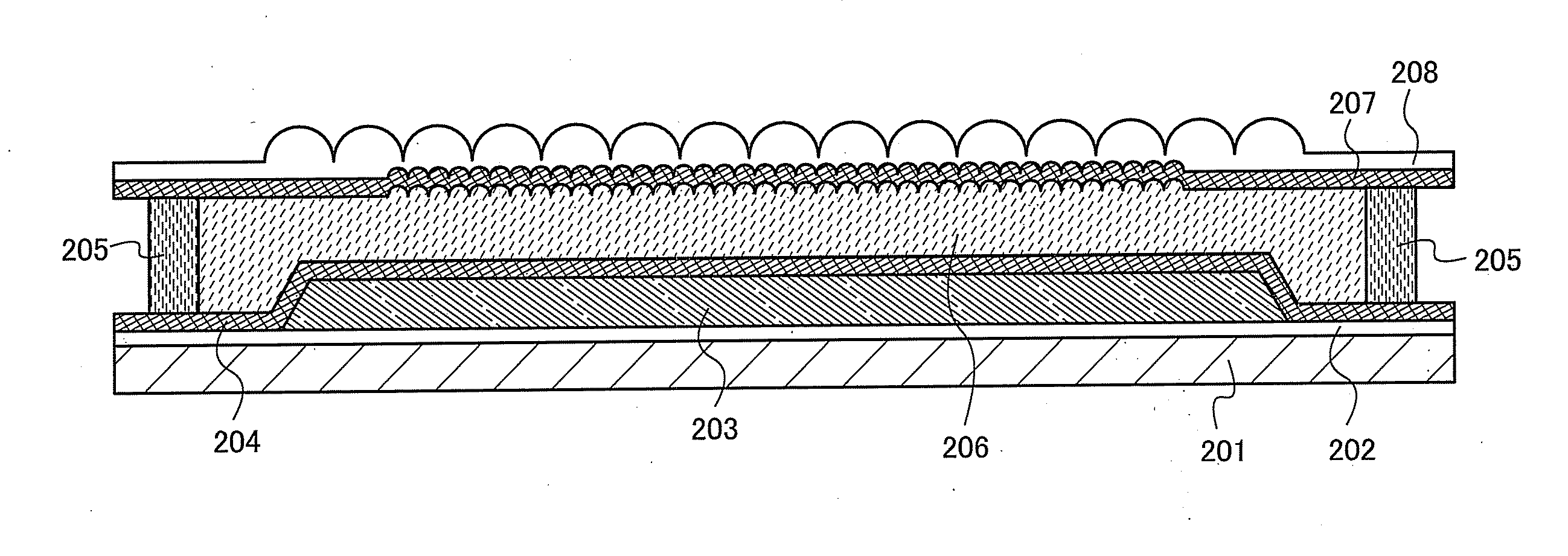
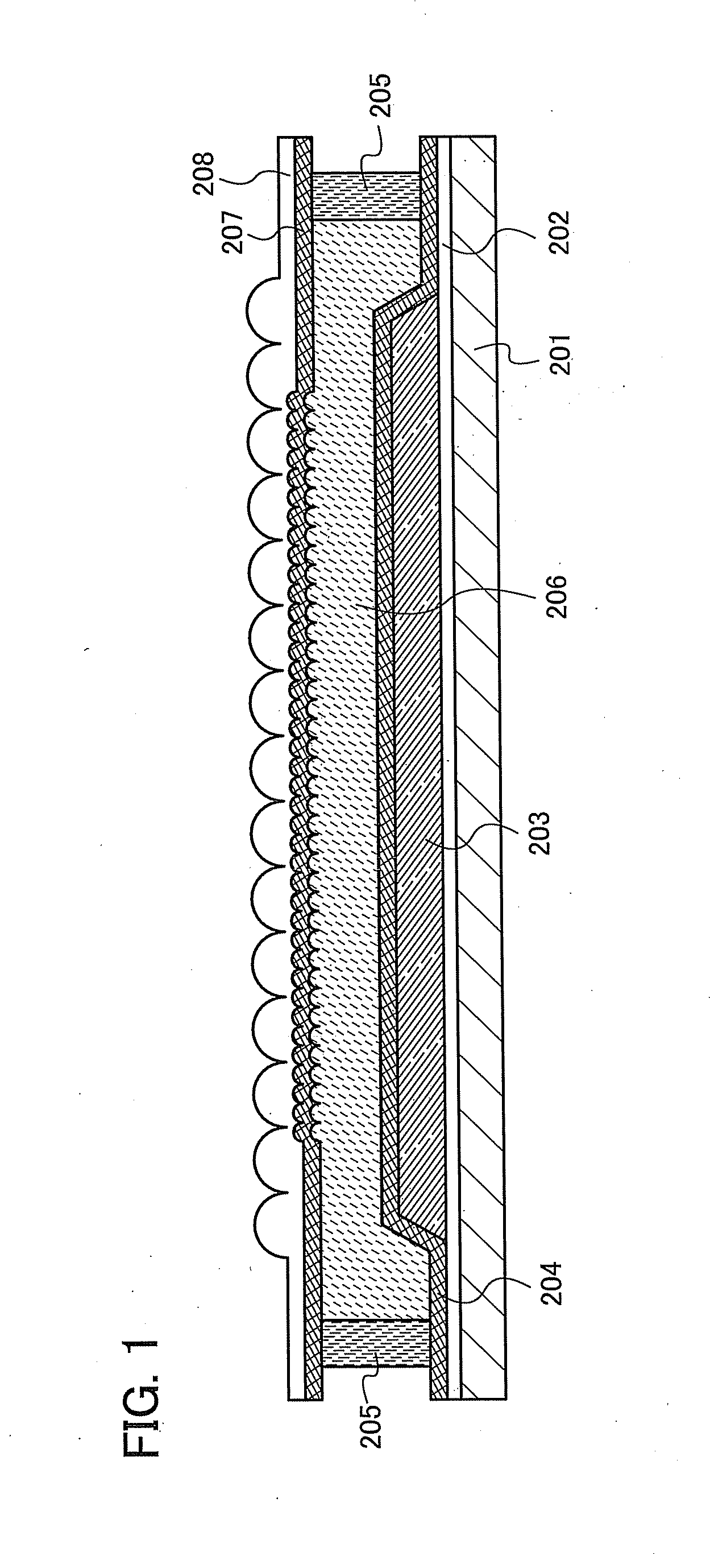
[0040]FIG. 1 is a cross-sectional view illustrating a lighting device of this embodiment. The lighting device illustrated in FIG. 1 includes a substrate 201, a base film 202, a first barrier layer 204 provided over the base film 202, and a light-emitting element layer 203 including an organic EL layer in a region surrounded by the base film 202 and the first barrier layer 204.

[0041]A second barrier layer 207 is provided over the first barrier layer 204. Further, a sealant 205 is provided between the first barrier layer 204 and the second barrier layer 207. The sealant 205 is formed over the first barrier layer 204 in a region where the light-emitting element layer 203 is not formed, and seals a resin layer 206 described later.

[0042]The resin layer 206 including a desiccant is provided in a region surrounded by the first barrier layer 204, the second barrier layer 207, and the sealant 205.

[0043]A resin substrate 208 which has a first uneven structure on a surface in contact with the ...

embodiment 2

[0168]In this embodiment, an application example of the lighting device described in Embodiment 1 will be described with reference to FIGS. 6A and 6B.

[0169]FIG. 6A illustrates an interior lighting device 901, an interior lighting device 904, and a desk lamp 903 to which one embodiment of the disclosed invention is applied. Since the lighting device according to one embodiment of the disclosed invention can have a large area, the lighting device can be used as a lighting device having a large area. In addition, the lighting device can be used as a roll-type lighting device 902.

[0170]FIG. 6B illustrates an example of another lighting device. A desk lamp illustrated in FIG. 6B includes a lighting portion 911, a support 913, a support base 915, and the like. The lighting portion 911 includes the lighting device described in Embodiment 1. As described above, in one embodiment of the present invention, a lighting device having a curved surface or a lighting device having a flexible lighti...


PUM


Abstract

The lighting device includes a layer containing a light-emitting organic compound which is provided over a substrate; a first barrier layer covering the layer containing a light-emitting organic compound; a second barrier layer provided over the first barrier layer; a sealant provided between the first barrier layer and the second barrier layer; a resin layer including a desiccant which is surrounded by the first barrier layer, the second barrier layer, and the sealant; and a resin substrate which is provided over the second barrier layer and has a first uneven structure on a surface in contact with the second barrier layer and a second uneven structure on a surface in contact with the air, and the second uneven structure has a larger height difference than the first uneven structure.

Description

BACKGROUND OF THE INVENTION[0001]1. Field of the Invention[0002]One embodiment of the disclosed invention relates to a lighting device using organic electroluminescence (EL).[0003]2. Description of the Related Art[0004]An organic EL element has been actively researched and developed. In the fundamental structure of the organic EL element, a layer containing a light-emitting organic compound is interposed between a pair of electrodes. By applying voltage to this element, light emission from the light-emitting organic compound can be obtained.[0005]The organic EL element can be formed into a film; thus, a large-area element can be easily formed. Therefore, the organic EL element has a high utility value as a surface light source that can be applied to lighting or the like.[0006]For example, a lighting device including an organic EL element is disclosed in Patent Document 1.REFERENCEPatent Document[0007][Patent Document 1] Japanese Published Patent Application No. 2009-130132SUMMARY OF...

Claims


Application Information

Patent Timeline
Patent Type & Authority Applications(United States)
IPC IPC(8): H01J1/63
CPCH01L27/3204H01L51/524H01L51/5246H01L51/5253H01L2251/558H01L51/5275H01L2251/5315H01L2251/5361H01L51/5259H10K59/86H10K50/846H10K50/841H10K50/8426H10K50/858H10K2102/3026H10K50/844H10K2102/351H01L21/0214H01L21/02145
Inventor TANAKA, KOICHIRONISHIDO, YUSUKE
Owner SEMICON ENERGY LAB CO LTD
Why Eureka
Try Eureka