Cooling system having reduced mass pin fins for components in a gas turbine engine

Inactive Publication Date: 2012-08-16
SIEMENS ENERGY INC
View PDF2 Cites 26 Cited by
  • Summary
  • Abstract
  • Description
  • Claims
  • Application Information

AI Technical Summary

Benefits of technology

[0006]This invention relates to a cooling system having one or more pin fins with reduced mass for a gas turbine engine. The cooling system may include one or more surfaces defining at least a portion of the cooling system. The pin fin may extend from the surface defining the cooling system and may have a noncircular cross-section taken generally parallel to the surface and may be configured such that at least part of an outer surface of the cross

Problems solved by technology

The increase stresses reduce the

Method used


Image

  • Cooling system having reduced mass pin fins for components in a gas turbine engine
  • Cooling system having reduced mass pin fins for components in a gas turbine engine
  • Cooling system having reduced mass pin fins for components in a gas turbine engine

Examples


Example

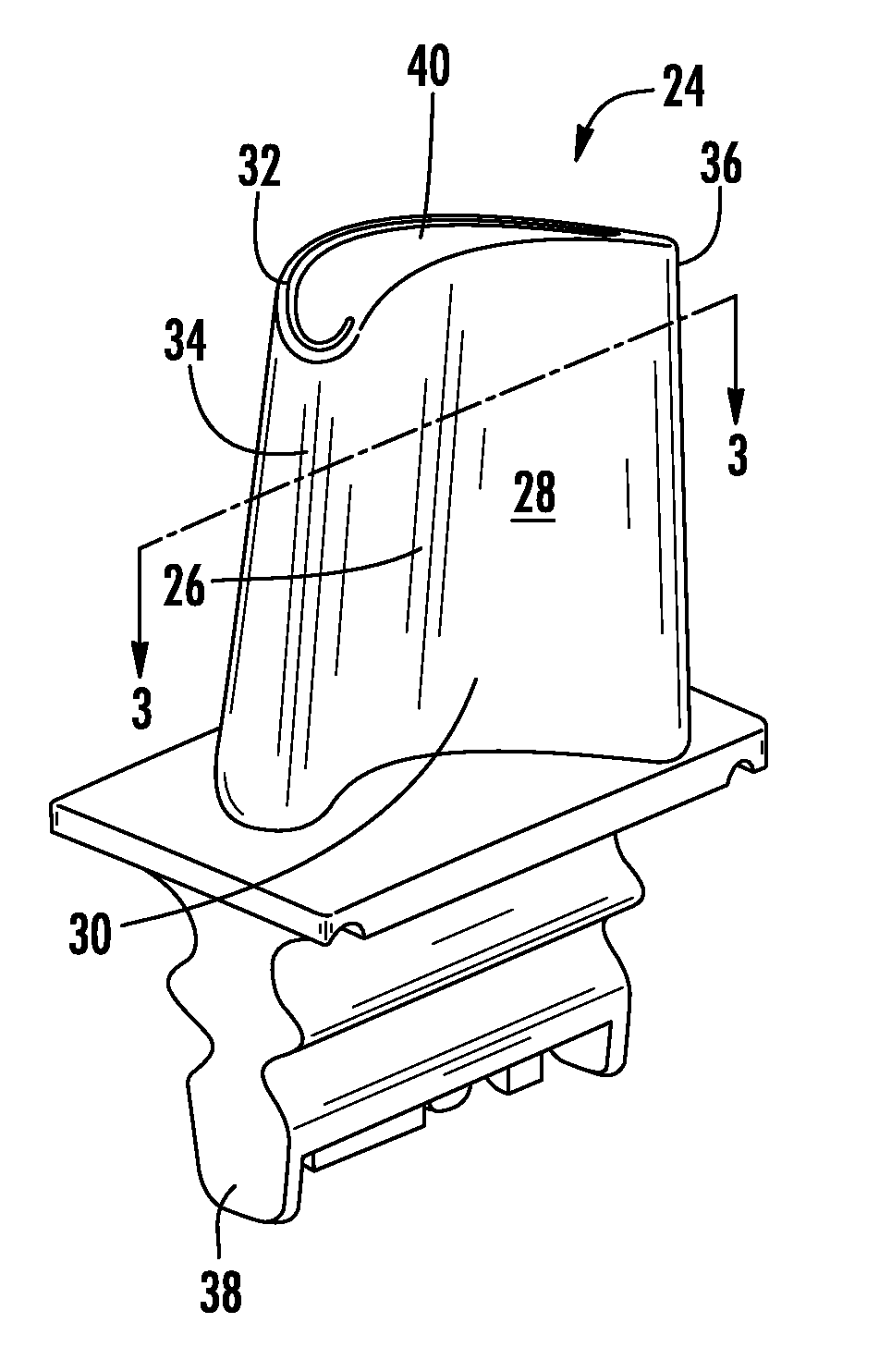
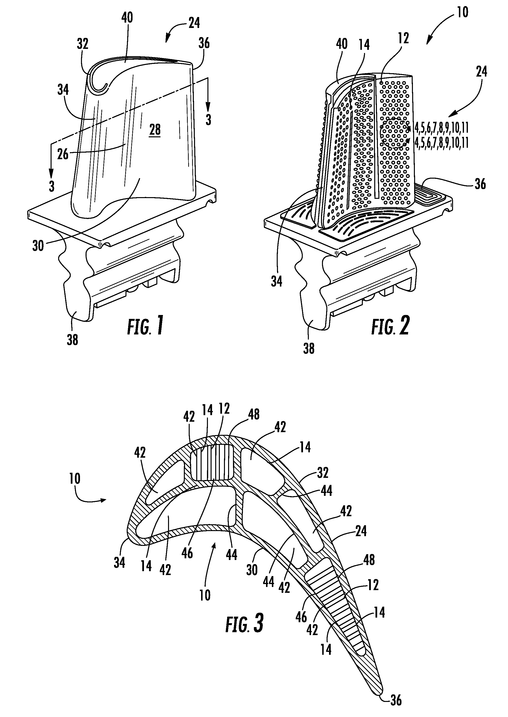
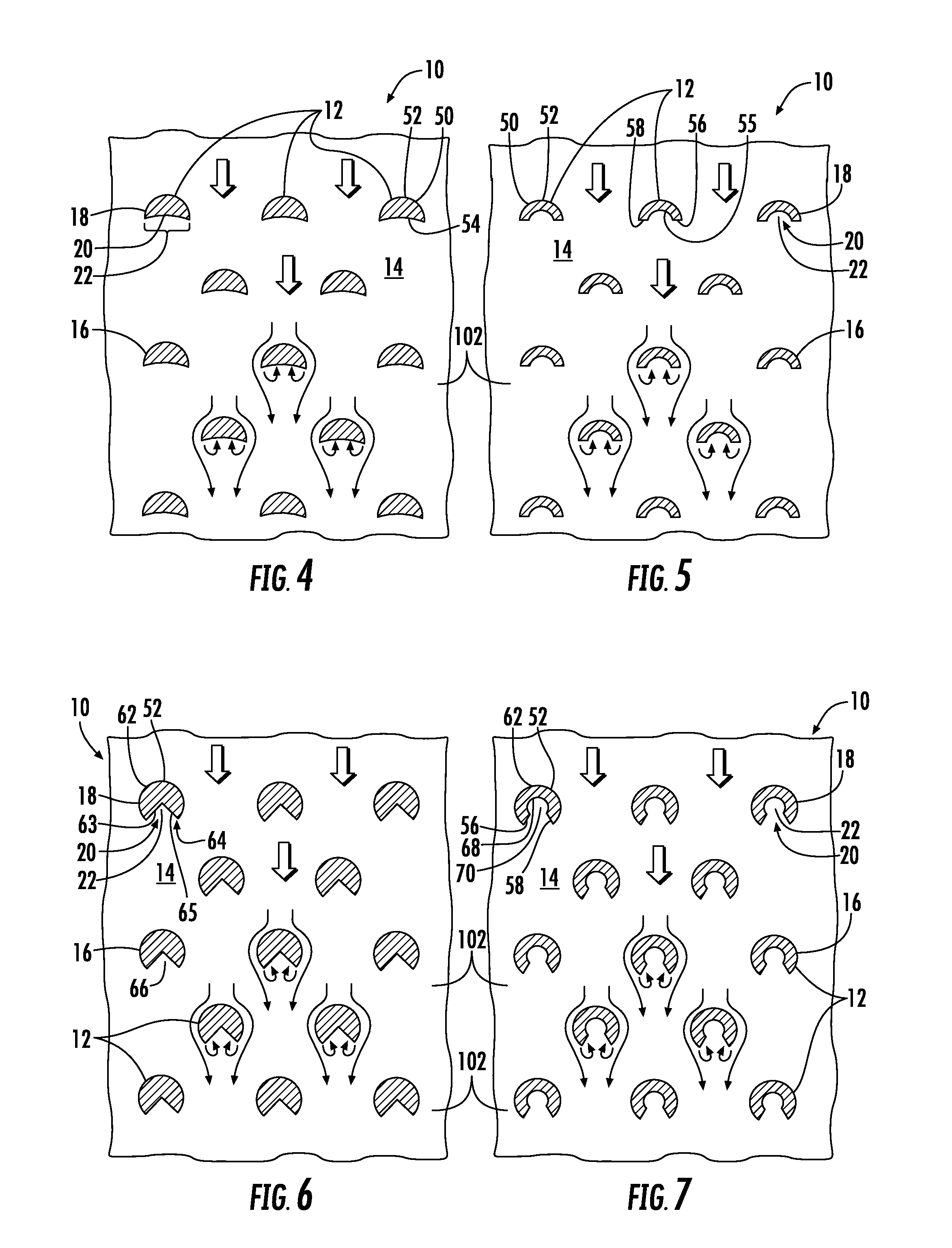
[0033]As shown in FIGS. 1-11, this invention is directed to a cooling system 10 having one or more pin fins 12 with reduced mass for a gas turbine engine. The cooling system 10 may include one or more surfaces 14 defining at least a portion of the cooling system 10. The pin fin 12 may extend from the surface 14 defining the cooling system 10 and may have a noncircular cross-section 16 taken generally parallel to the surface 14 and at least part of an outer surface 18 of the cross-section 16 forms at least a quartercircle. A downstream side 20 of the pin fin may have a cavity 22 to reduce mass. The cooling system 10 may be used in various components of a gas turbine engine, such as, but not limited to, a turbine blade 24, a turbine vane, a transition duct and a combustion liner. When used in a turbine blade, the cooling system 10 with reduced mass pin fins 12 generates less centrifugal stresses, thereby creating a more efficient turbine blade 24.

[0034]In one embodiment, the cooling s...


PUM


Abstract

A cooling system having one or more pin fins with reduced mass for a gas turbine engine is disclosed. The cooling system may include one or more first surfaces defining at least a portion of the cooling system. The pin fin may extend from the surface defining the cooling system and may have a noncircular cross-section taken generally parallel to the surface and at least part of an outer surface of the cross-section forms at least a quartercircle. A downstream side of the pin fin may have a cavity to reduce mass, thereby creating a more efficient turbine airfoil.

Description

STATEMENT REGARDING FEDERALLY SPONSORED RESEARCH OR DEVELOPMENT[0001]Development of this invention was supported in part by the United States Department of Energy, H2 Program, Contract No. DE-FC26-05NT42644. Accordingly, the United States Government may have certain rights in this invention.FIELD OF THE INVENTION[0002]This invention is directed generally to gas turbine engines with internal cooling systems, and more particularly to components of gas turbine engines having cooling channels for passing fluids, such as air, to cool the airfoils.BACKGROUND[0003]Typically, gas turbine engines include a compressor for compressing air, a combustor for mixing the compressed air with fuel and igniting the mixture, and a turbine blade assembly for producing power. Combustors often operate at high temperatures that may exceed 2,500 degrees Fahrenheit. Typical turbine combustor configurations expose turbine vane and blade assemblies to these high temperatures. As a result, turbine vanes and bla...

Claims


Application Information

Patent Timeline
IPC IPC(8): F01D5/14
CPCF01D5/187F05D2210/33F05D2260/2212F05D2250/32F05D2250/70F05D2240/127
Inventor LEE, CHING-PANGJIANG, NANMARRA, JOHN J.
Owner SIEMENS ENERGY INC
Why Eureka
Try Eureka