Fuel pump

a fuel pump and fuel technology, applied in the field of fuel pumps, can solve the problems of increasing costs, increasing the number of parts, and performing on the pump housing, and achieve the effect of low cos

Inactive Publication Date: 2012-08-16
TOYOTA JIDOSHA KK
View PDF10 Cites 14 Cited by
  • Summary
  • Abstract
  • Description
  • Claims
  • Application Information

AI Technical Summary

Benefits of technology

[0040]Accordingly, the fuel pump of the invention is able to be a small fuel pump that is cable of controlling the discharge amount and discharge pressure by providing the reed valve body and the operating member that operates this reed valve body. In addition, there is no need to manufacture a high precision poppet valve body and valve seat hole and the like. As a result, a small, low cost fuel pump capable of controlling the discharge amount and discharge pressure can be provided.

Problems solved by technology

However, when a plurality of valves are housed in a fuel pump in this way, and each of these valves is formed with a valve body, a valve seat, a spring, a guide, and a stopper, and the like, as a poppet valve or the like is, the number of parts becomes even larger and complicated hole-drilling must be performed on the pump housing, which increases costs.
However, even in this case, the annular through-hole in the valve plate and the seat plates acts as a spillway for controlling the discharge amount and discharge pressure of the fuel and is opened and closed by a poppet valve type electromagnetic spill valve, which results in an increase in the number of parts and requires high precision valve seat hole drilling just the same, so costs are unable to be sufficiently reduced.

Method used


Image

  • Fuel pump
  • Fuel pump
  • Fuel pump

Examples


Embodiment Construction

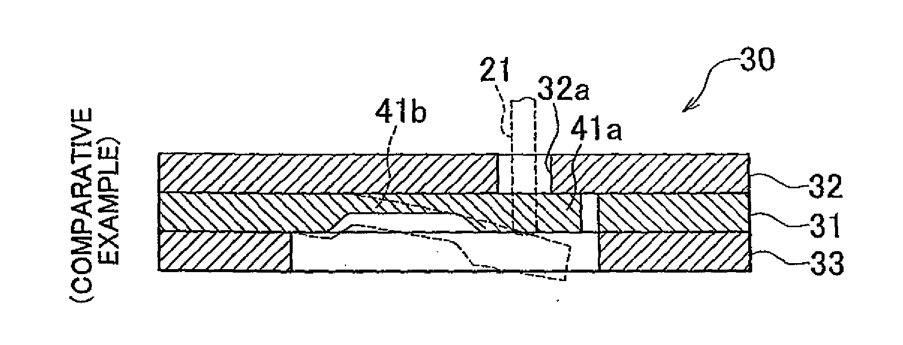
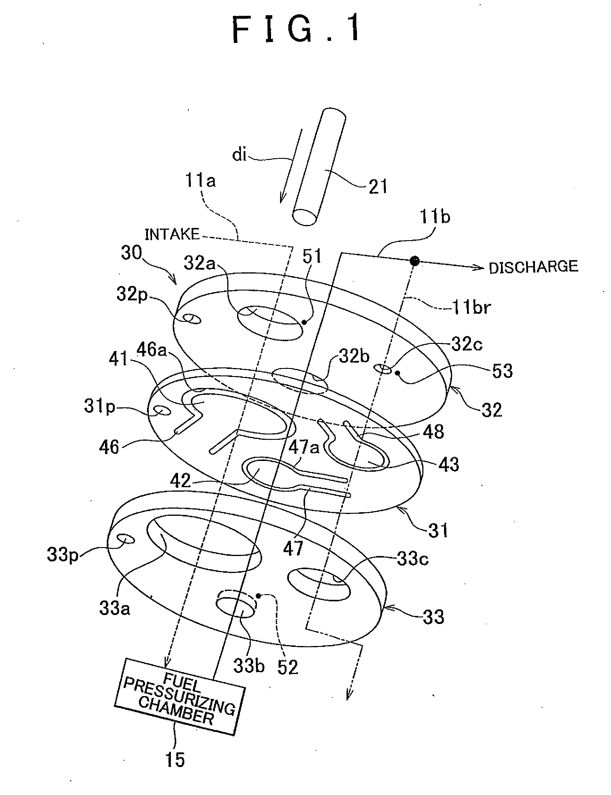
[0073]Example embodiments of the present invention will be described in greater detail below with reference to the accompanying drawings. FIGS. 1 to 4 show a fuel pump according to a first example embodiment of the invention.

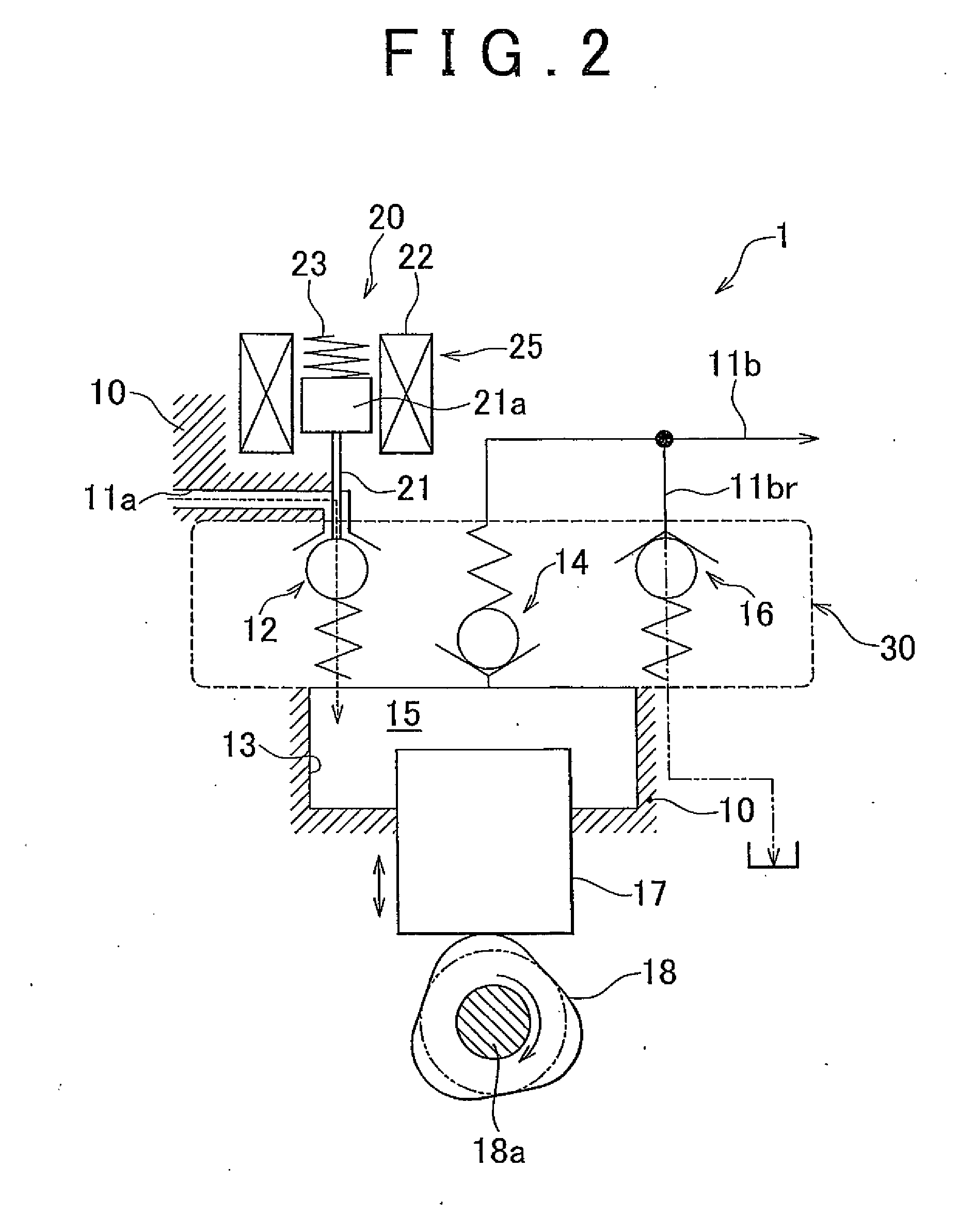
[0074]Incidentally, the fuel pump of this example embodiment is a plunger pump type high pressure fuel pump that draws in, pressurizes, and then discharges fuel for an engine such as an in-cylinder injection or dual injection type gasoline engine (hereinafter, simply referred to as “engine”) mounted in a vehicle, -according to the structure described below.

[0075]As schematically shown by the block diagram in FIG. 2, this fuel pump 1 is provided with a pump housing 10 (not shown in detail) that has a fuel passage 11a on the intake side (i.e., an intake passage), a fuel passage 11b on the discharge side (i.e., a discharge passage), and an internal space 13 that is communicated with both the fuel passage 11a and the fuel passage 11b.

[0076]A plunger 17 is housed so...


PUM


Abstract

In a fuel pump that includes a pump housing (10) that has fuel passages (11a, 11b), a plunger (17) that is movably housed in the pump housing (10), a fuel pressurizing chamber (15) that is formed in the pump housing (10) and draws in fuel via one of the fuel passages (11a) that is on the intake side of the fuel pressurizing chamber (15), pressurizes the fuel that has been drawn in, and discharges the pressurized fuel via the other fuel passage (11b) that is on the discharge side of the fuel pressure chamber (15), in response to movement of the plunger (17), and valve elements (12, 14, 16) that are arranged in the fuel passages (11a, 11b) near the fuel pressurizing chamber (15), each of the valve elements (12, 14, 16) has a reed valve body (41, 42, 43; 74, 75, 76) arranged in the fuel passage (11a) on the intake side of the fuel pressurizing chamber (15) or the fuel passage (11b) on the discharge side of the fuel pressurizing chamber (15); and an operating member (21) that applies operating force in at least one of a valve opening direction or a valve closing direction to the reed valve body (41, 42, 43; 74, 75, 76) is provided in the pump housing (10).

Description

BACKGROUND OF THE INVENTION[0001]1. Field of the Invention[0002]The invention relates to a fuel pump that pressurizes fuel for an internal combustion engine to a high pressure and then discharges it. More particularly, the invention relates to a plunger pump in which a valve that controls the flow and pressure of fuel is provided near a fuel pressurizing chamber of the plunger pump.[0003]2. Description of the Related Art[0004]Recently, among internal combustion engine for vehicles, so-called direct-injection types that inject fuel directly into the cylinders, even with spark-ignition systems, have become popular. Of these, some attempt to increase output by increasing the intake air amount by cooling the intake air through the vaporization heat of fuel injected into the cylinders during the intake stroke, and improve combustion stability during startup with semi-stratified combustion achieved by injecting fuel into the cylinders during the compression stroke.[0005]In these type of i...

Claims


Application Information

Patent Timeline
Patent Type & Authority Applications(United States)
IPC IPC(8): F04B23/00
CPCF02M59/366F02M59/462F02M59/464F02M59/466F02M63/005F16K15/185F04B1/0465F04B7/0076F04B39/1073F04B53/1037F16K15/16F02M63/0265F16K15/1825
Inventor USUI, TAKASHIKITAMURA, TAKESHIYOKOYAMA, HIROKAZUTANAKA, YOSHIHIRO
Owner TOYOTA JIDOSHA KK
Why Eureka
Try Eureka