Endoscope apparatus and method of setting reference image of endoscope apparatus

a technology of endoscope and reference image, which is applied in the field of endoscope apparatus and a method of setting a reference image of the endoscope apparatus, can solve problems such as damage or malfunction of the endoscop

Inactive Publication Date: 2012-08-16
OLYMPUS CORP
View PDF26 Cites 7 Cited by
  • Summary
  • Abstract
  • Description
  • Claims
  • Application Information

AI Technical Summary

Benefits of technology

[0016]According to yet another aspect of the present invention, there can be provided a method of acquiring a reference image of an endoscope apparatus, including displaying on a display section a message for instructing light shielding of an image pickup section provided at a distal end portion of a scope so as to prevent light from entering the image pickup section, heating the image pickup section so that a temperature of the image pickup section reaches a predetermined temperature, driving the image pickup section with the temperature of the image pickup section kept at the predetermined temperature to acquire a reference image, and storing the acquired reference image in a predetermined memory.

Problems solved by technology

On the other hand, when the endoscope apparatus is used in a harsh working environment, the scope may be damaged or malfunction.

Method used


Image

  • Endoscope apparatus and method of setting reference image of endoscope apparatus
  • Endoscope apparatus and method of setting reference image of endoscope apparatus
  • Endoscope apparatus and method of setting reference image of endoscope apparatus

Examples


second embodiment

[0103]Next, a configuration of an endoscope apparatus according to a second embodiment of the present invention will be described.

1. Configuration

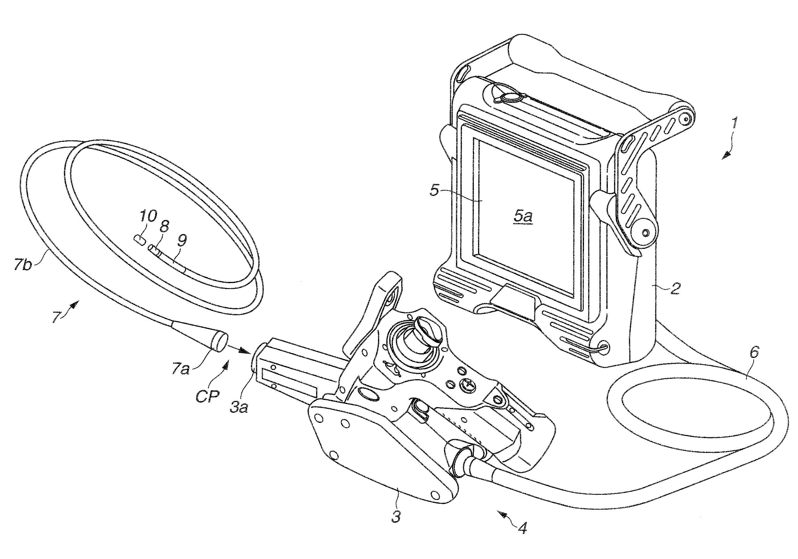
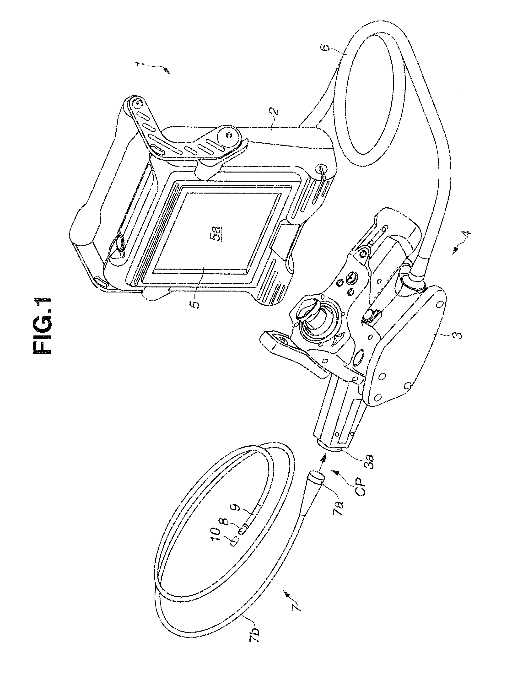
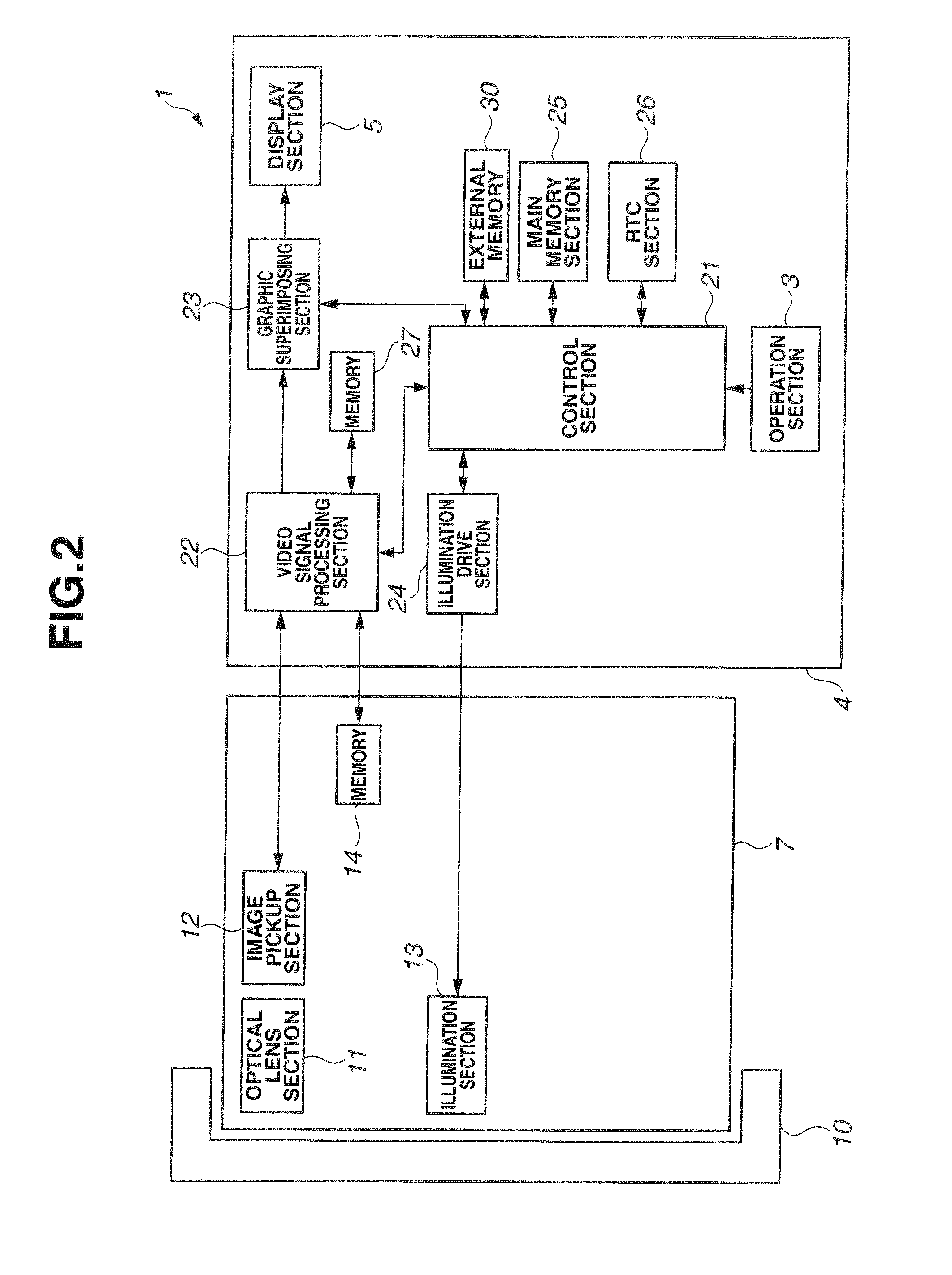
[0104]An outside view of the endoscope apparatus according to the second embodiment is similar to that in FIG. 1 of the first embodiment. The configuration of the endoscope apparatus according to the second embodiment is also similar to the configuration in FIG. 2, but has a different configuration as shown in FIG. 12. Therefore, in the second embodiment, the same components as those in the first embodiment will be assigned the same reference numerals and descriptions thereof will be omitted.

[0105]FIG. 12 is a block diagram schematically illustrating a configuration of an endoscope apparatus 1A of the present embodiment. As described above, the endoscope apparatus 1A is constructed of the main body 4 and the scope 7, and the light-shielding adapter 10 can be attached to the distal end of the scope 7.

[0106]The scope 7 is configured by inclu...

modification examples

3. Modification Examples

[0140]Next, modification examples of the aforementioned second embodiment will be described.

modification example 1

[0141]According to the aforementioned embodiment, the initialization processing is performed in the case where a different scope is detected when the power to the endoscope apparatus 1A is turned on first and a different scope is detected, and in the case where no different scope is detected and initialization is instructed.

[0142]Without being limited thereto, however, a menu screen may be displayed separately when the power to the endoscope apparatus 1A is turned on and the endoscope apparatus 1 is operating in a normal operation state, that is, while a live image is being displayed on the screen 5a of the display section 5, and the user may be instructed to select initialization from the menu screen so that the initialization processing from S25 onward is performed.


PUM


Abstract

An endoscope apparatus 1 includes a main body 4 to which a scope having an image pickup device at a distal end portion 8 of an insertion portion 7b is detachably attachable, a video signal processing section 22, a display section 5 and a control section 21. The control section 21 displays on the display section 5 a message for instructing a user to light-shield the distal end portion 8 according to an instruction for starting initialization processing to acquire a reference image of the image pickup device, acquires the reference image with the distal end portion 8 light-shielded and stores the acquired reference image in a memory 27.

Description

CROSS REFERENCE TO RELATED APPLICATION[0001]This application claims benefit of Japanese Application No.2011-28859 filed in Japan on Feb. 14, 2011, and No. 2011-28860 filed in Japan on Feb. 14, 2011, the contents of which are incorporated by this reference.BACKGROUND OF THE INVENTION[0002]1. Field of the Invention[0003]The present invention relates to an endoscope apparatus and a method of setting a reference image of the endoscope apparatus.[0004]2. Description of the Related Art[0005]Endoscope apparatuses are being widely used in an industrial field and a medical field. There are endoscope apparatuses configured with a scope having an insertion portion with an image pickup device provided at a distal end portion thereof and a main body to which the scope is detachably connected.[0006]A user can inspect an object by causing the distal end portion of the elongated insertion portion to approach a vicinity of the object and causing an image picked up by an image pickup device to be dis...

Claims


Application Information

Patent Timeline
Patent Type & Authority Applications(United States)
IPC IPC(8): A61B1/04
CPCA61B1/05A61B1/00057
Inventor NUMATA, KENJI
Owner OLYMPUS CORP
Why Eureka
Try Eureka