
Quality Control System And Method For Manufactured Parts

Inactive Publication Date: 2012-08-16
ABB TECH AG
View PDF11 Cites 11 Cited by
  • Summary
  • Abstract
  • Description
  • Claims
  • Application Information

AI Technical Summary

Benefits of technology

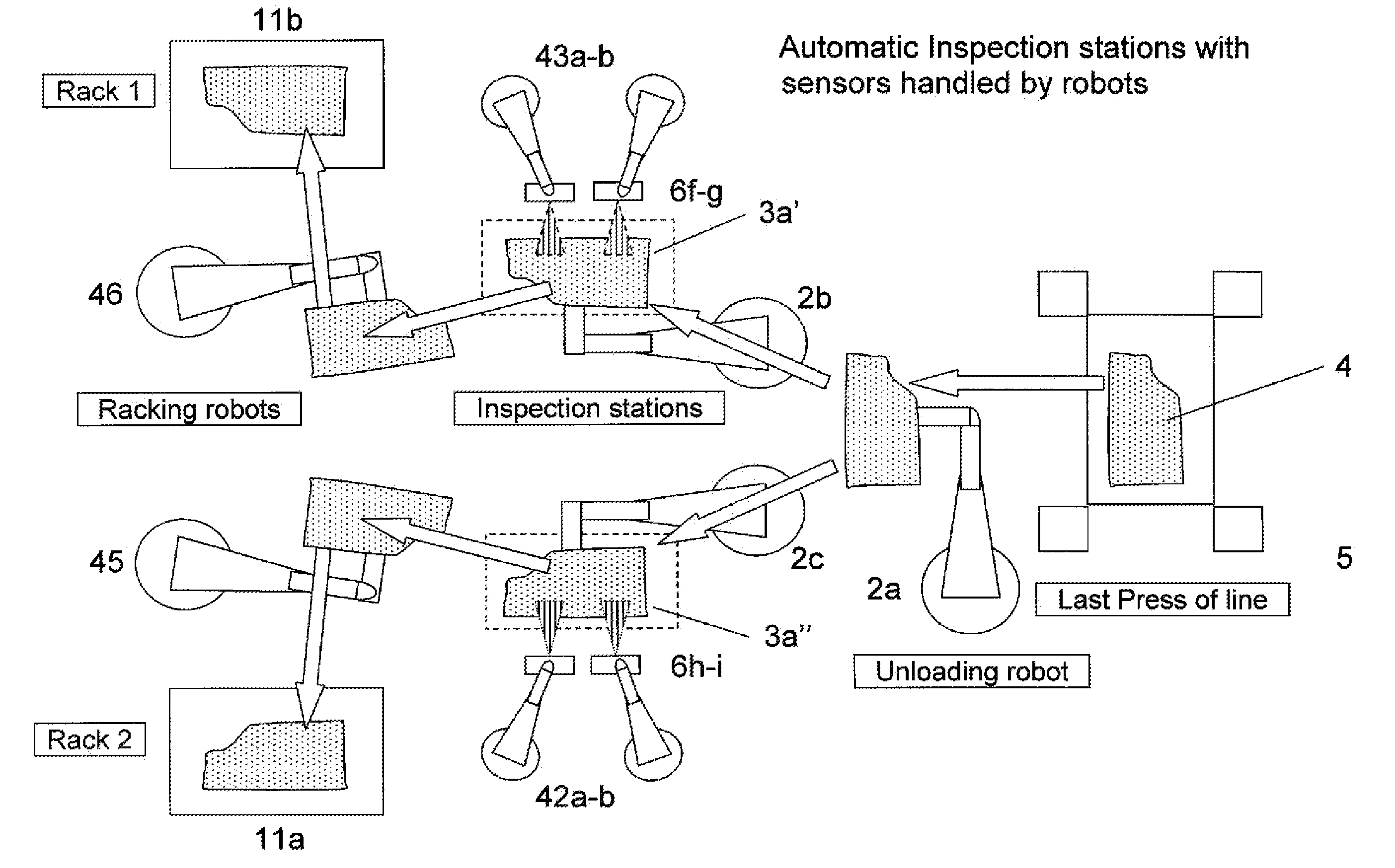
[0036]In the case of automatic inspection, the robot presents the part to an automatic Quality Inspection station consisting of one or more sensors. The sensors can be of different types, appropriate for detecting different types of defects. One or more sensors can also be handled by a small second robot or manipulator to provide additional flexibility to the system.
[0037]As the part is, at any moment, handled by robots, one of the main key values of an aspect of the invention is to maintain the information of its position, facilitating the completion of the whole process, which is a great improvement compared to traditional concepts in which the part location is lost and needs to be relocated in order for the part to continue in the process. Our proposed concept also eliminates the need of conveyors or complex conveyors, in which the position is lost, eliminating therefore the need of vision re-locating system or mechanical centering.
[0038]Also, in the case of manual inspection, as the robot handles the part, this can be presented to the operator in the right orientation to optimize his accessibility for the inspection. This provides a health and safety benefit for operators because the orientation and position can be optimized in for example an ergonomic way. This will reduce unnecessary movement or strain by the operator that may, for example, otherwise cause operator fatigue. Presentation by the robot also improves the technical aspects of the inspection because inspection for, e.g., surface defects requires that the surface be viewed with adequate lighting and in a consistent way. The robot always presents the part in the optimal position and orientation for quality inspection.
[0040]To be more concrete and as example to illustrate the advantages of our concept, we will focus on the application in a Press-shop, where several type of defects (like scratches, creases, cracks, etc.) need to be detected. Thus a surface defect on a stamped door skin panel may be corrected at low cost if detected immediately. Early detection also makes it possible to correct a problem before other parts are manufactured with a defect. The technical challenges and the cost much is greater if detection does not take place until a later stage, such as if the panel is mounted on an automobile and painted before the fault is detected.
[0041]Applying our concept to the case of automotive skin panels, the whole process is considerably simplified. The unloading robot, instead of placing the part on a belt conveyor, presents the part to another (or sequentially to more than one) robot. When transferring the part from one to another robot, the part is normally turned-over. This is to be able to present the correct surface for which the quality inspection is required. As the unloading robot usually picks up the part from the side to be inspected (the upper side) it is convenient that the robot hands it to another robot because a turning over of the part takes place in the handover. In this way, also, the unloading robot may split the flow of stamped parts by alternative handover to two or more robots that will work in parallel, each one presenting the part to one quality inspection station. Depending on the available cycle time, the same robots can place the parts on the rack or container or transfer to one other robot, or splitting that task as well and handing over to in two or more robot(s) to do it.

Problems solved by technology

This cost grows exponentially with the detection of faults within later or subsequent production processes.
In this last case the operation might be really complex since the robot in charge of the operation must first locate the part on the conveyor for a correct picking.
The part might be unstable and could require a complex arrangement with a triple band belt conveyor with adjustable height in central band to provide the required stability to keep the part from moving about.

Method used


Image

  • Quality Control System And Method For Manufactured Parts
  • Quality Control System And Method For Manufactured Parts
  • Quality Control System And Method For Manufactured Parts

Examples


Embodiment Construction

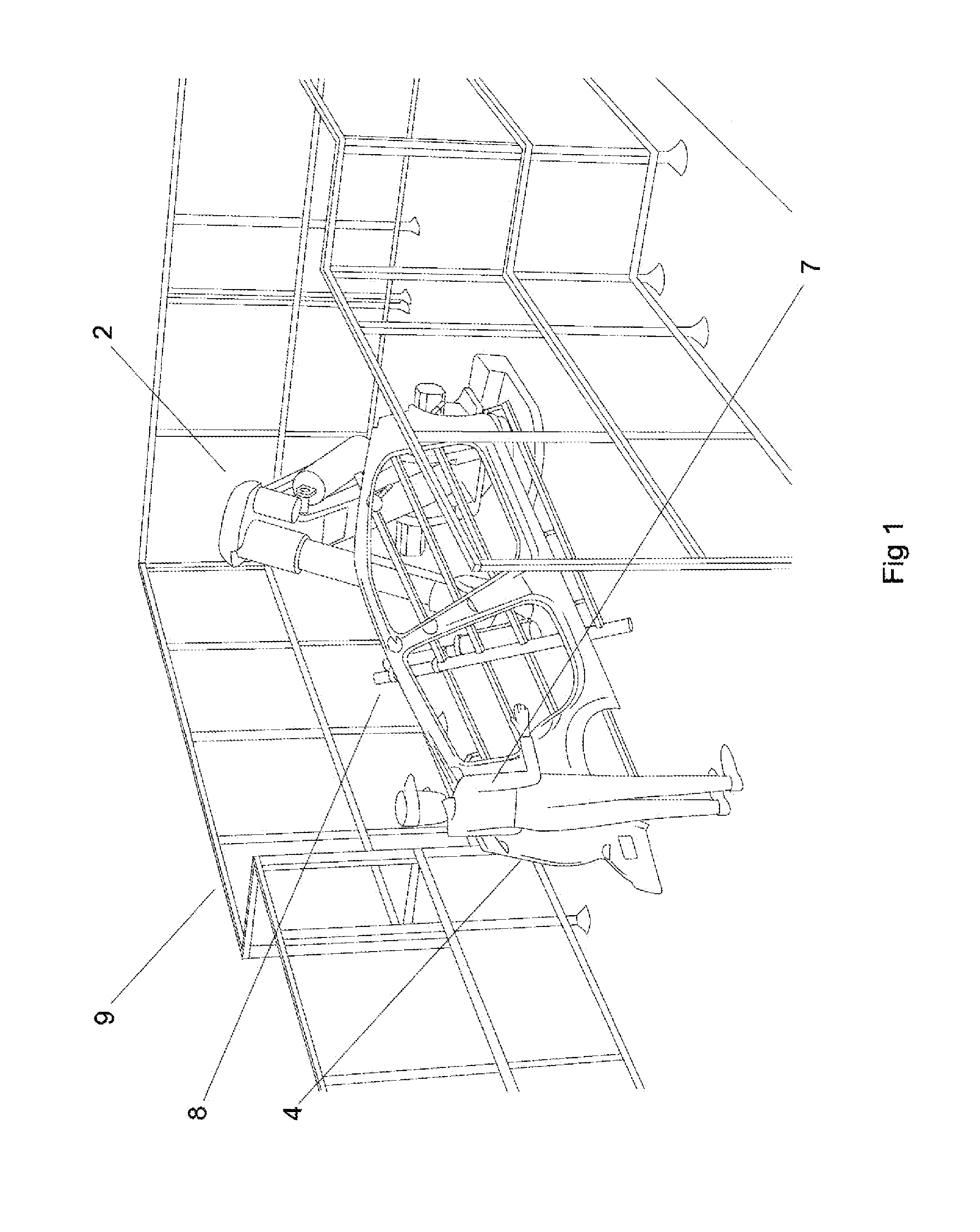
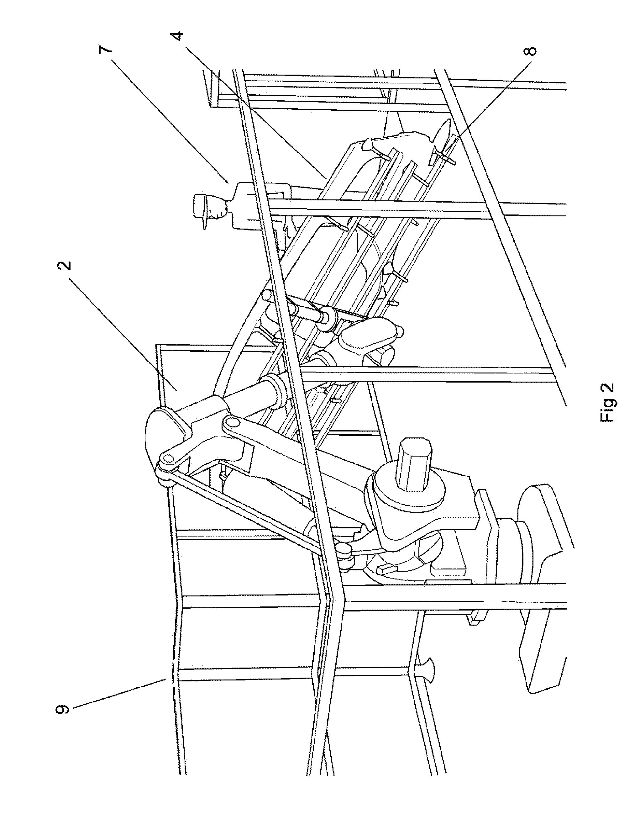
[0051]FIGS. 1 and 2 show two computer simulated views of a quality inspection cell 9 including an industrial robot 2 which is arranged for manual inspection. The industrial robot 2 is arranged with a handling tool 8, which may be a gripper, used to pick up a part 4 manufactured in production process (not shown here see FIGS. 3, 5, 8-10). The inspection cell functions in the following way. The industrial robot 2 picks up the part 4 with handling tool 8 from the production process (not shown) and moves it to at least one known position, fixed and pre-programmed in advance, thus predetermined in the quality inspection cell. First the robot moves the part 4 to the at least one known position relative to where an operator 7 shall be positioned. The safety issues in this process are described below. The robot holds the part or, so as to say, presents the part to the operator so that the operator can make an inspection efficiently and simply. The robot holds the part in exactly the right o...


PUM


Abstract

A system and method for production of manufactured parts including a production process having at least one industrial robot equipped with a handling tool for picking up the manufactured part. The robot is arranged in a quality inspection cell and the robot is programmed to hold the manufactured part in at least one known position in the quality inspection cell and present the part for a quality inspection. The quality inspection may be made visually by an operator or with the aid of a tool or sensor or by means of automatic sensors. In other aspects of the invention a method, system and a computer program for carrying out the method are described.

Description

CROSS-REFERENCE TO RELATED APPLICATIONS[0001]The present application is a continuation of pending International patent application PCT / EP2010 / 062957 filed on Sep. 3, 2010 which claims the benefit under 35 U.S.C. §119 (e) of U.S. Provisional Patent Application Ser. No. 61 / 244,233, filed on Sep. 21, 2009. The content of all prior applications is incorporated herein by reference.FIELD OF THE INVENTION[0002]The present invention is concerned with a method for carrying out a quality inspection on a manufactured part. In particular it is concerned with quality inspection which is carried out automatically in part by an industrial robot.BACKGROUND OF THE INVENTION[0003]Quality Inspection is required in many different areas of industry, for example Automotive, White goods, Foundries, Welding operations, Painted products, Food production, Pharmaceutical production and others. Companies are striving to decrease the Cost of Poor Quality (CoPQ) while increasing the quality of products offered t...

Claims


Application Information

Patent Timeline
IPC IPC(8): G06F19/00B25J15/06B25J15/00
CPCB25J9/0084G01N21/9515G01N21/8803B25J19/06B25J15/00B25J19/00
Inventor CASANELLES, RAMONGRAU, FRANCESC CORTES
Owner ABB TECH AG
Learn More