Turbine Nozzle Blade and Steam Turbine Equipment Using Same

a turbine blade and turbine technology, applied in the direction of machines/engines, stators, mechanical equipment, etc., can solve the problems that the reduction effect of secondary flow loss has been unlikely to be fully brought about by the conventional technique, and achieve the effects of reducing the number of blades, reducing secondary flow loss, and improving the efficiency of the turbine stag

Inactive Publication Date: 2012-08-23
MITSUBISHI HITACHIPOWER SYST LTD
View PDF4 Cites 25 Cited by
  • Summary
  • Abstract
  • Description
  • Claims
  • Application Information

AI Technical Summary

Benefits of technology

[0009]The above configuration enables supply of a turbine nozzle blade in which reducing the number of blades is effective for reducing secondary-flow loss in addition to profile loss, and hence for improving t...

Problems solved by technology

JP-2008-202420-A, however, does not describe on a stagger angle of the blades and on a load distribution in an axial chord direction...

Method used


Image

  • Turbine Nozzle Blade and Steam Turbine Equipment Using Same
  • Turbine Nozzle Blade and Steam Turbine Equipment Using Same
  • Turbine Nozzle Blade and Steam Turbine Equipment Using Same

Examples


first embodiment

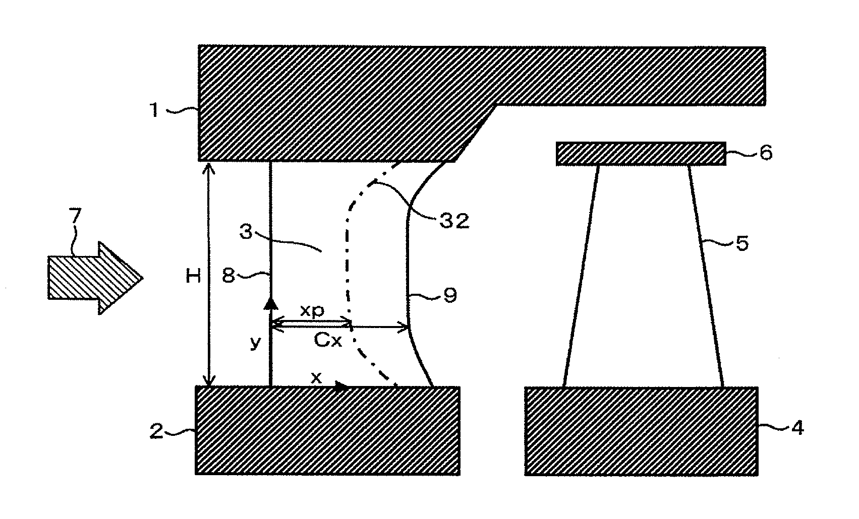
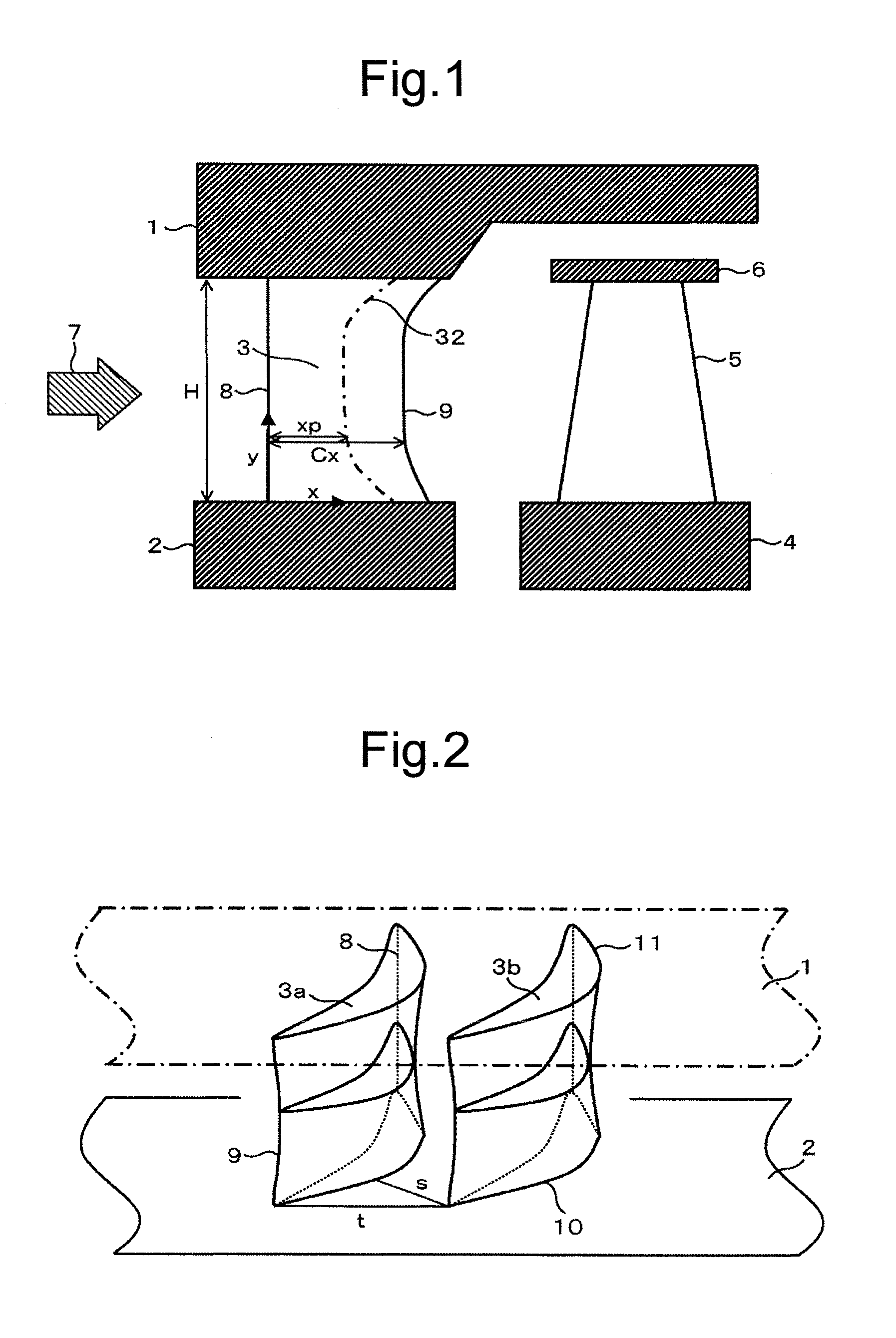
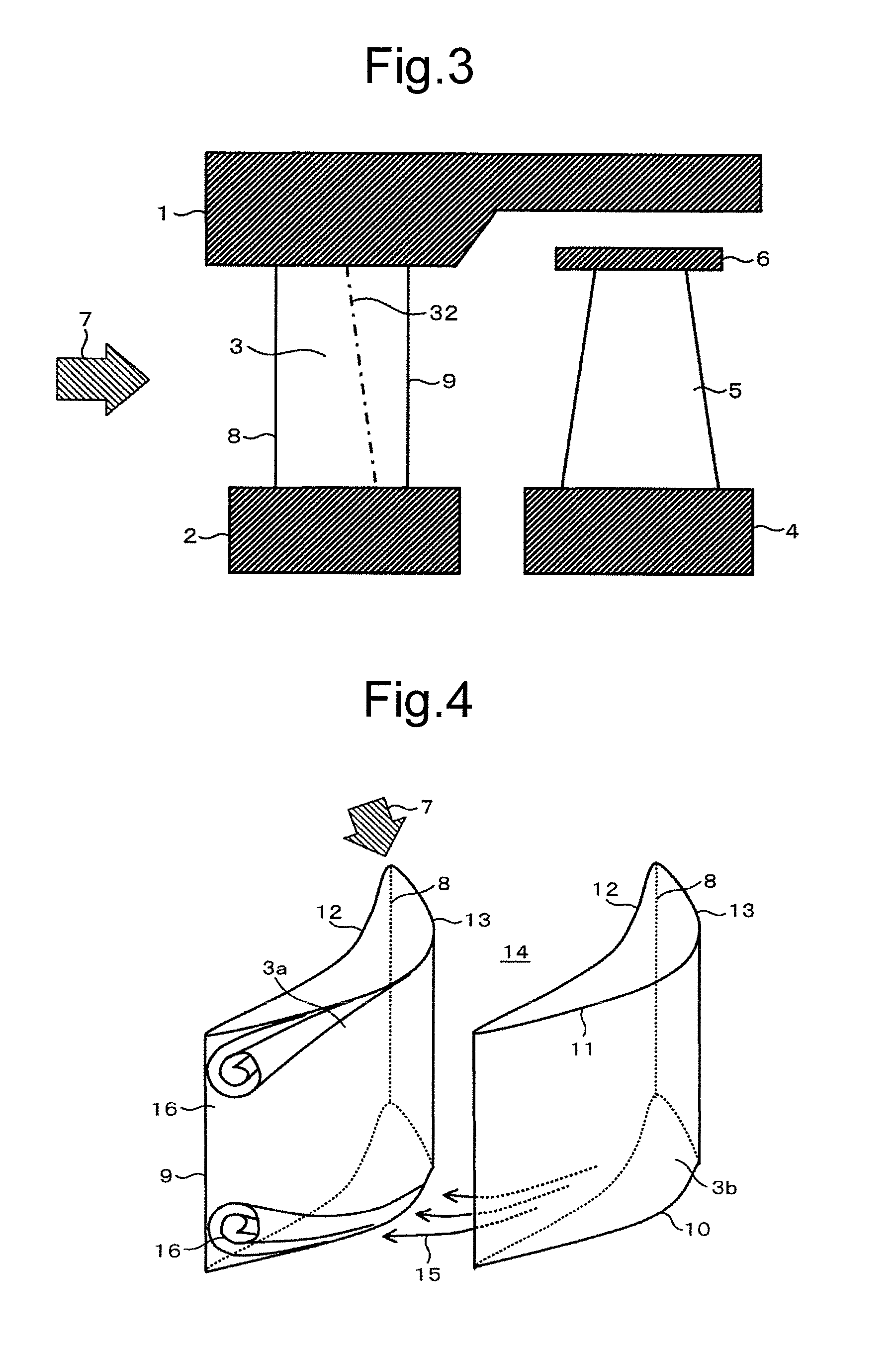
[0023]A first embodiment of the present invention is described below. FIG. 1 is a cross-sectional view showing a structure of a steam turbine stage section according to the present embodiment. As shown in FIG. 1, the steam turbine stage section according to the present embodiment includes a plurality of nozzle blades 3 each disposed in a circumferential direction of the turbine, between a diaphragm outer ring 1 and a diaphragm inner ring 2. The steam turbine stage section also includes a plurality of rotor blades 5 each disposed in a circumferential direction of a turbine rotor 4, at a downstream side of a flow direction of steam relative to one of the nozzle blades 3. The downstream side of the flow direction of steam relative to the nozzle blade 3 is hereinafter referred to simply as the downstream side. The radially outer side of the turbine is hereinafter referred to simply as the outer side. A shroud 6 is provided at a tip of each rotor blade 5, at a radially outer side of the ...

second embodiment

[0042]A second embodiment of the present invention is shown in FIG. 8. Differences from the foregoing embodiment are mainly described below.

[0043]The second embodiment relates to a blade of large H / Cx, a ratio between blade height H and axial chord length “Cx.” This cascade is equivalent to long blades having a significant difference in radius between the blade tip and hub. In this case, in order to minimize the difference in “t / Cx” (i.e., the difference in load coefficient) between the tip and hub of the blade, “Cx” has been traditionally increased according to a particular radius R. When the present invention is applied to such a case, the hub includes a portion at which, as the radius increases, “d Cx / d R” decreases relative to the distribution of “Cx” that originally has a tendency to increase, and the tip includes a portion at which, as the radius increases, “d Cx / d R” also increases more than at a mid-span position. In other words, the present embodiment is characterized in th...


PUM


Abstract

Disclosed is a highly efficient turbine nozzle blade that reduces the number of blades in an axial-flow turbine while reducing secondary-flow loss. In the nozzle blade, when a differential pressure between a pressure side and a suction side of each blade, at the same axial chord position of the blade, is defined as a load of the blade, and a ratio between axial chord length “Cx” of the blade and an axial distance “xp” from a leading edge of the blade at a maximum load position that maximizes the blade load is defined as a maximum load relative position, Cx is greater at a hub and tip than at an intermediate vertical portion, and simultaneously a maximum load relative position at the hub and tip is set to be nearer to a trailing edge thereof than a maximum load relative position of the intermediate vertical portion of the blade.

Description

BACKGROUND OF THE INVENTION[0001]1. Field of the Invention[0002]The present invention relates to a turbine nozzle blade used for axial-flow turbines, especially gas turbines, steam turbines, and the like, at electric power plants.[0003]2. Description of the Related Art[0004]In recent years, it is strongly requested to further enhance turbine performance for the purpose of an improvement in electric-power generating efficiency at power plants. Turbine performance is involved in the stage loss, exhaust loss, and mechanical loss of the turbine, and it is considered to be most effective to reduce the stage loss, in particular, for turbine performance improvement. There are various types of stage loss. Such stage loss can be roughly categorized, namely, (a) profile loss due to the blade shape itself, (b) secondary-flow loss due to a working fluid flow not along a main flow of the working fluid, and (c) leakage loss caused by leakage of the working fluid from the main flow. The secondary-...

Claims


Application Information

Patent Timeline
IPC IPC(8): F01D5/14F01K13/00
CPCF01D5/141F01D9/041F05D2240/12F05D2240/122F05D2220/31Y02T50/60
Inventor SHIBATA, TAKANORISEGAWA, KIYOSHIKISHIBE, TADAHARUKIMURA, SEIICHILEE, GOINGWON
Owner MITSUBISHI HITACHIPOWER SYST LTD
Why Eureka
Try Eureka