Eureka AIR delivers breakthrough ideas for toughest innovation challenges, trusted by R&D personnel around the world.

Sensor Arrangement for a Vehicle and Corresponding Method for Producing such a Sensor Arrangement

Inactive Publication Date: 2012-08-23
ROBERT BOSCH GMBH
View PDF5 Cites 14 Cited by
  • Summary
  • Abstract
  • Description
  • Claims
  • Application Information

AI Technical Summary

Benefits of technology

[0007]In a refinement of the sensor arrangement according to the invention, the star contour of the sensor housing body is hot caulked with the corresponding star contour of the insertion sleeve. The hot caulking can advantageously ensure a desired functional dimension and a durable connection between the components.
[0009]In a further refinement of the sensor arrangement according to the invention, a cap with at least one cut-out for the connecting cable is provided. In this context, the cap covers the bent region of the connecting cable and is fitted over the fastening tab and latched. In order to secure all the parts, the cap is pushed onto the fastening tab and latched. In this context, the radial forces from the connecting cable are not absorbed by the latched connection but rather by an encompassing geometry. The cap advantageously serves as a fastening element and as a heat protection for the bending point of the connecting cable.

Problems solved by technology

It is therefore possible, for example, for new mold inserts and / or adjustment of mold inserts to be necessary, as a result of which the molds become very complex and high-maintenance.

Method used


Image

  • Sensor Arrangement for a Vehicle and Corresponding Method for Producing such a Sensor Arrangement
  • Sensor Arrangement for a Vehicle and Corresponding Method for Producing such a Sensor Arrangement
  • Sensor Arrangement for a Vehicle and Corresponding Method for Producing such a Sensor Arrangement

Examples


Embodiment Construction

[0023]In the accompanying FIGS. 1 to 10, identical reference symbols denote throughout elements and / or components which carry identical or analogous functions.

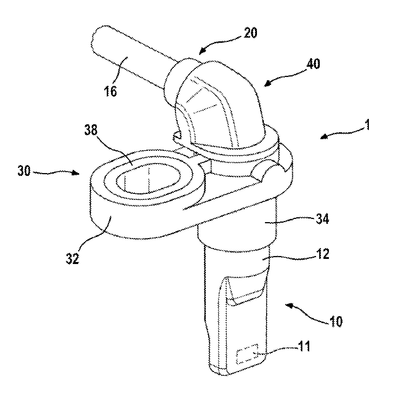
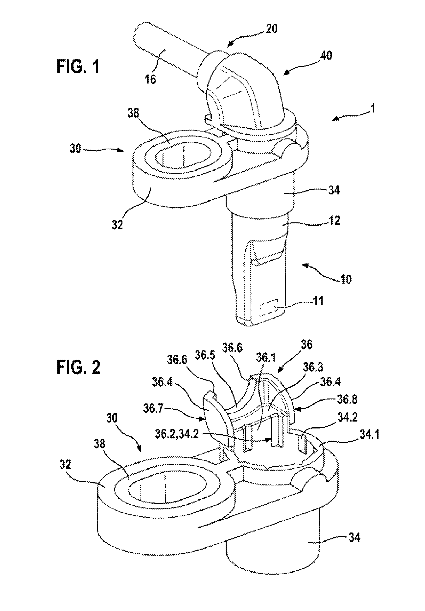
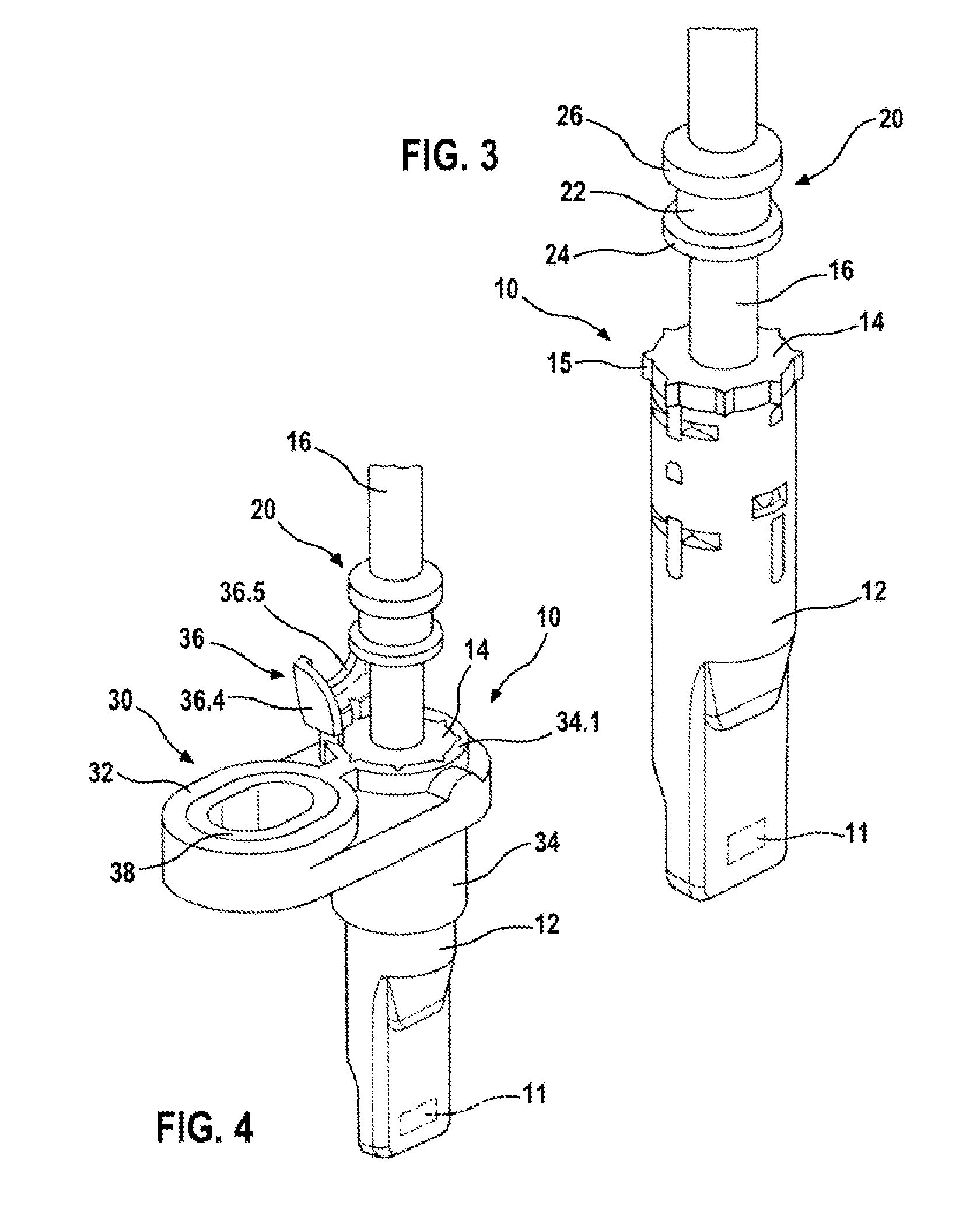
[0024]FIG. 1 illustrates a first exemplary embodiment of a sensor arrangement 1 with a sensor element 11 and / or an electrical assembly for detecting and evaluating measurement signals, in particular magnetic field signals, a fastening tab 30, a connecting cable 16 and cap 40. The sensor element 11 and the connecting cable 16 have been at least partially encased with plastic by injection molding in order to form a sensor housing 10. The sensor housing 10 is connected to the fastening tab 30 which comprises a base body 32 with a fastening bush 38 which is arranged to the side of the cable outlet. In addition, the fastening tab 30 comprises an insertion sleeve 34 which is connected to the base body 32 and into which a sensor housing body 12 of the sensor housing 10 is inserted. The sensor housing 10 and the insertion sleeve 34 ea...


PUM

PropertyMeasurementUnit
Timeaaaaaaaaaa

Abstract

A sensor arrangement for a vehicle includes a sensor element and a connection cable at least partially encased with plastic by means of injection moulding in order to form a sensor housing. The sensor housing is connected to a fastening tab which comprises a base body having fastening means. The fastening tab includes an insertion sleeve which is connected to the base body and into which a sensor housing body of the sensor housing is inserted. The sensor housing and the insertion sleeve each comprise fixing means which are designed in such a manner that there are different angular positions for fixing the sensor housing and the fastening tab. The sensor housing and the fastening tab are fixed in one of the different angular positions with respect to one another.

Description

PRIOR ART[0001]The invention is based on a sensor arrangement for a vehicle of the generic type of independent patent claim 1 and on a corresponding method for producing such a sensor arrangement of independent patent claim 7.[0002]German Laid-Open Patent Application DE 10 2008 042 091 A1 describes a method for producing a magnetic field sensor and a corresponding magnetic field sensor, in particular for use as a rotational speed sensor and / or direction of rotation sensor for the rotation of the wheel or for the drive train of a motor vehicle. The described magnetic field sensor comprises an electrical assembly for sensing and evaluating magnetic field signals and a connecting cable, which are together encased in plastic in an injection molding process. At the same time, a fastening tab is integrally molded on, which fastening tab has a base body with a fastening bush. The described production method uses fabrication methods which are proven for the production of sensors with an axi...

Claims


Application Information

Patent Timeline
IPC IPC(8): G01D11/24B23P11/00
CPCH04L1/0003H04L1/0009H04L1/0015Y10T29/49826H04L1/0035H04L1/18H04L2001/0097H04L1/0026
Inventor STEINBRINK, RONALDMATTHIE, DANIELBEYERSDORFER, JAN
Owner ROBERT BOSCH GMBH
Why Eureka
Eureka Blog
Learn More