Tensioning Device for a Safety Belt

a technology of a safety belt and a tensioning device, which is applied in the direction of vehicle safety belts, belt retractors, vehicle components, etc., can solve the problems of affecting the motion sequence affecting the safety of the vehicle, and affecting the operation of the tensioning device. , to achieve the effect of increasing the force-limiting level, reducing pressure peaks, and high tensioning for

Active Publication Date: 2012-08-23
AUTOLIV DEV AB
View PDF2 Cites 8 Cited by
  • Summary
  • Abstract
  • Description
  • Claims
  • Application Information

AI Technical Summary

Benefits of technology

[0008]The advantage of the proposed solution is that the opening is closed or has a constricted cross-section at the start of the tensioning operation so that a high tensioning force can be transmitted at that time. The opening is then opened by the pressure and / or the flow conditions prevailing in the pressure space during the tensioning operation so that the pressure prevailing in the pressure space can escape through the open and / or enlarged opening in the piston. Owing to the open and / or enlarged opening, pressure peaks can be reduced without adversely affecting the tensioning operation and the piston can be moved back in a reverse direction against the tensioning motion after the tensioning operation without again increasing the force-limiting level. According to the present invention, the effect of the material wear or erosion caused by gas flow is used for opening and / or enlarging the opening, with the advantage that during the tensioning operation the free cross-section of the opening is continuously enlarged and / or is still closed at the start of the tensioning operation and only opened during the tensioning operation. It is thus possible to transmit a high tensioning force of the tensioning device at the start of the tensioning operation and reduce the pressure prevailing in the pressure space at the end of the tensioning operation as quickly as possible in order to prevent the destruction of the force limiter. The material wear, also called erosion, is caused by the pressure and / or flow conditions prevailing in the pressure space so that the opening and / or enlargement of the opening is directly activated by the tensioning device itself. In this connection, the nominal size of the opening and / or enlargement of the opening is directly related to the pressure, which ultimately results in the detrimental behavior of the tensioning device in case of an excessive pressure increase. In case the pressure is substantially lower for some reason, that is, the disadvantages described above do not occur, the opening is not opened, or opened to a lesser degree, so that in this case the tensioning force is still not unnecessarily reduced. The effect of the material erosion can also be supported by the prevailing temperature conditions and the particles resulting from the activation of the gas generator.

Problems solved by technology

The problem with generic seat belt retractor tensioning devices of the pyrotechnically activated-type is that the pressure conditions during the tensioning operation vary considerably.
In particular, very high pressure peaks can damage parts of the tensioning device, or disturb the motion sequences of the tensioning device.
Furthermore, the problem is that, unless the safety belt is provided with a force limiting device, the belt force at the start of the force-limited belt extension motion following the tensioning operation increases for a short time to a force limiting level that is higher than that defined by the force limiting device due to the pressure still prevailing in the tensioning device.
The production of both the blind opening and the through-opening is expensive and requires a complex assembly process which further increases the price of the tensioning device.
In this connection, the nominal size of the opening and / or enlargement of the opening is directly related to the pressure, which ultimately results in the detrimental behavior of the tensioning device in case of an excessive pressure increase.
In case the pressure is substantially lower for some reason, that is, the disadvantages described above do not occur, the opening is not opened, or opened to a lesser degree, so that in this case the tensioning force is still not unnecessarily reduced.

Method used


Image

  • Tensioning Device for a Safety Belt
  • Tensioning Device for a Safety Belt
  • Tensioning Device for a Safety Belt

Examples


Embodiment Construction

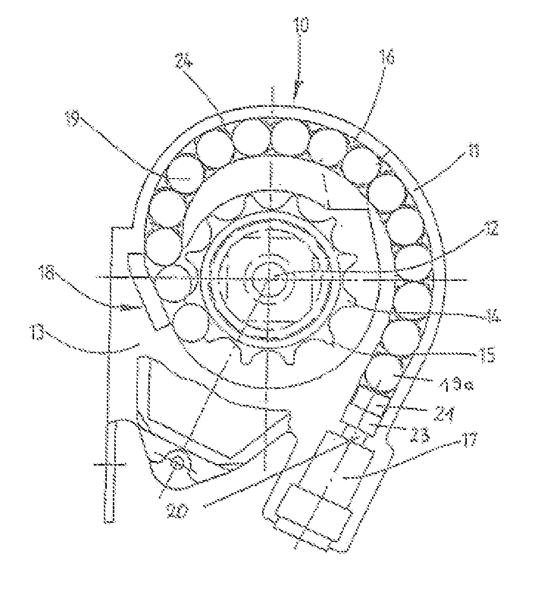
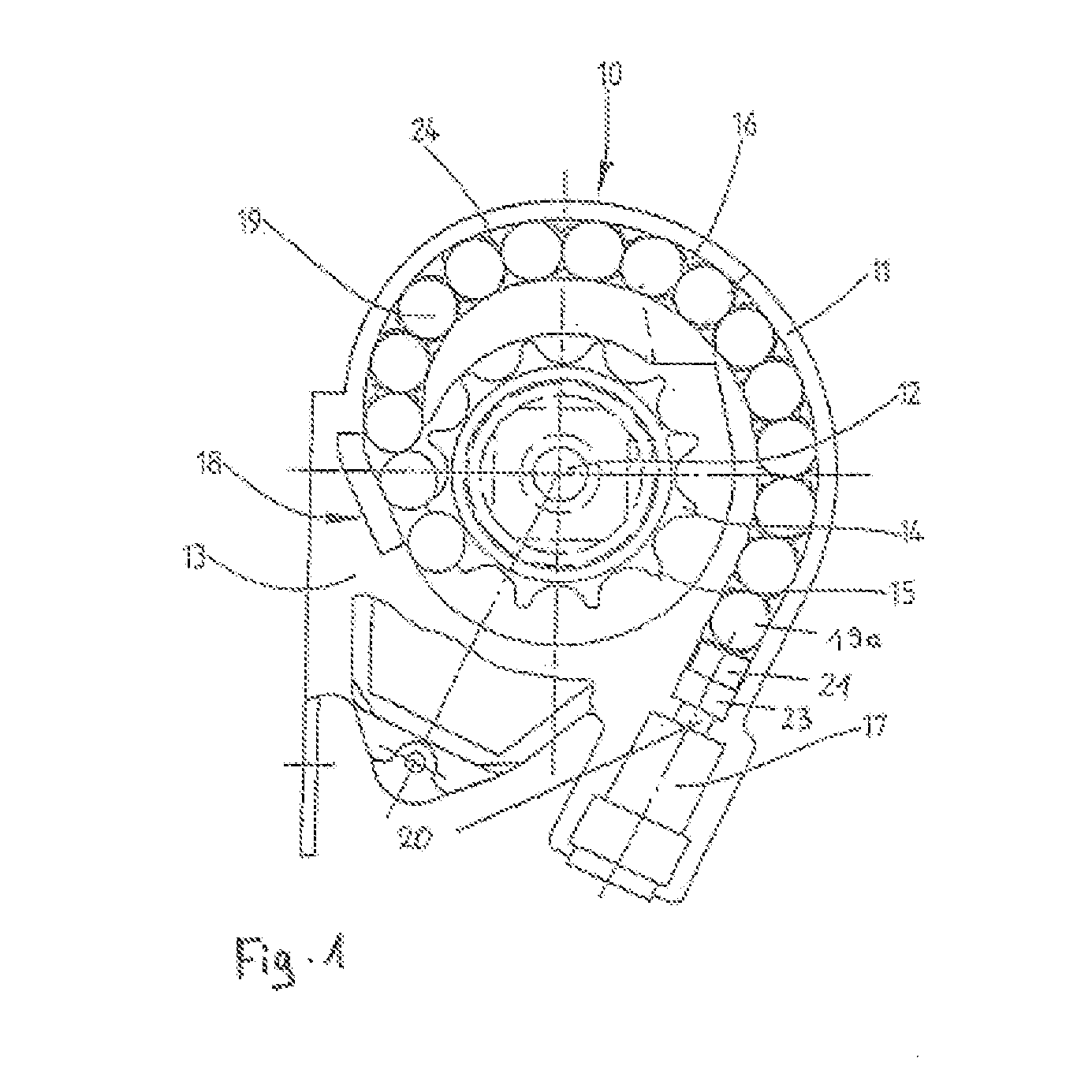
[0018]The belt retractor schematically shown in FIG. 1 comprises a housing 11 with a side piece 13, a belt retractor shaft 12 for a seat belt strap, which is not shown, mounted therein and a tensioning device 10 acting on the belt retractor shaft 12 after being activated. The tensioning device 10 comprises a drive wheel 14 connected in a torque transmitting manner to the belt retractor shaft 12, the drive wheel 14 having, for example, external teeth, a pyrotechnical gas generator 17 to generate the gas pressure, and a tube 16 connecting the gas generator 17 to the belt retractor shaft 12 via the drive wheel 14. The tube 16 is formed by a tube wall 24 which is part of the housing 11, or alternatively also by a separate component.

[0019]A series of balls 19, preferably made of metal is provided in the tube 16 to transmit the gas pressure generated by the gas generator 17 to the belt retractor shaft 12 via the drive wheel 14. The belt retractor is not restricted with respect to the embo...


PUM


Abstract

A tensioning device (10) for a seat belt, in particular in a motor vehicle, having a gas generator (17) and a piston (21) guided in a tube (16) that closes a pressure space (20) in the tube (16), whereas the pressure space (20) can be pressurized by the gas generator (17), as a result of which the piston (21) can be driven to perform a tensioning operation which can be transmitted to the seat belt by means of the force transmission means. The piston (21) having a closed or constricted opening (1, 1a), and the opening (1, 1a) can be enlarged and/or opened by the material erosion caused by the pressure and/or pressure conditions in the pressure space (20).

Description

CROSS-REFERENCE TO RELATED APPLICATIONS[0001]This application claims priority to German Patent Application No. 10 2009 051 451.1, filed Oct. 30, 2009 and PCT / EP2010 / 006227, filed Oct. 12, 2010.FIELD OF THE INVENTION[0002]The invention relates to a tensioning device for a seat belt, in particular in a motor vehicle.BACKGROUND OF THE INVENTION[0003]The problem with generic seat belt retractor tensioning devices of the pyrotechnically activated-type is that the pressure conditions during the tensioning operation vary considerably. In particular, very high pressure peaks can damage parts of the tensioning device, or disturb the motion sequences of the tensioning device. Furthermore, the problem is that, unless the safety belt is provided with a force limiting device, the belt force at the start of the force-limited belt extension motion following the tensioning operation increases for a short time to a force limiting level that is higher than that defined by the force limiting device du...

Claims


Application Information

Patent Timeline
Patent Type & Authority Applications(United States)
IPC IPC(8): B60R22/46
CPCB60R22/4628B60R2022/4642B60R22/1954B60R2022/4661
Inventor FISCHER, CHRISTIANSCHMIDT, MARTINSTEINBERG, MATTHIASPECH, MICHAELVOSS, TOBIASSCHMIDT, THOMASMESECKE-RISCHMANN, SIMONE
Owner AUTOLIV DEV AB
Why Eureka
Try Eureka