BLDC motor for a hairdryer

a bldc motor and hair dryer technology, applied in the direction of machines/engines, magnetic circuit rotating parts, magnetic circuit shapes/forms/construction, etc., can solve the problems of increased weight of bldc motor b>20/b>, long service life, inconvenient use, etc., to reduce manufacturing costs, reduce weight of bldc motor, and high strength

Active Publication Date: 2012-08-23
JMW
View PDF16 Cites 10 Cited by
  • Summary
  • Abstract
  • Description
  • Claims
  • Application Information

AI Technical Summary

Benefits of technology

[0012]According to embodiments of the present invention, a BLDC motor includes high strength plastic parts integrated through injection molding. Thus, the number of parts is decreased to thereby decrease manufacturing costs, and the weight of the BLDC motor is decreased to thereby improve use convenience of a hair dryer.
[0013]In addition, a support protrusion and a removal prevention protrusion are disposed in a coupling portion between a base bracket and a bearing housing, to thereby stably support a stator core. Thus, an inner diameter of the stator core is decreased, and a winding width of a coil is increased, thus maximizing efficiency of the BLDC motor.
[0014]In addition, an auxiliary fan functioning as a turbo fan is integrated into a sirocco fan of the BLDC motor, thereby decreasing energy consumption and noises. In addition, a housing coupling ring for coupling to a rotor housing is provided to the sirocco fan, thereby rotating the sirocco fan more stably.

Problems solved by technology

Since BLDC motors do not require a brush, the service life thereof is long.
In addition, since most of parts are formed of metals, the total weight of the BLDC motor 20 is increased, and thus is inconvenient to use.
Furthermore, a sirocco fan installed on a shaft fan of a typical BLDC motor to forcibly blow air is coupled to a rotor housing through a pin, or is coupled to the central portion thereof, and thus, may be unstably rotated.

Method used


Image

  • BLDC motor for a hairdryer
  • BLDC motor for a hairdryer
  • BLDC motor for a hairdryer

Examples


Embodiment Construction

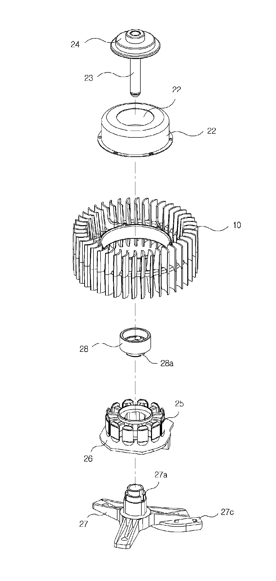
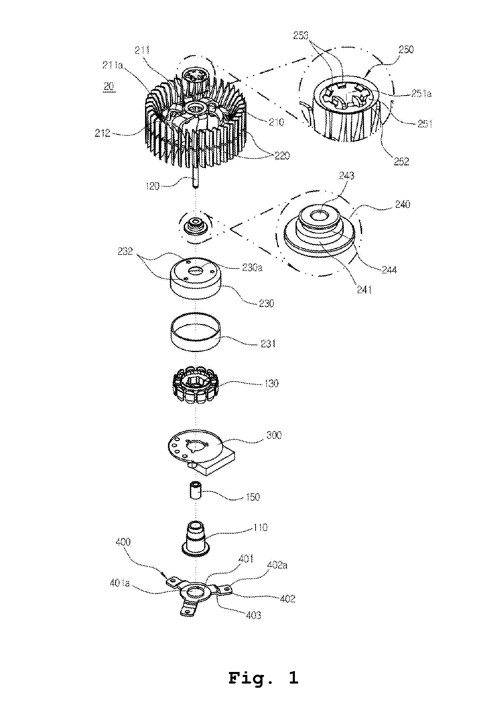
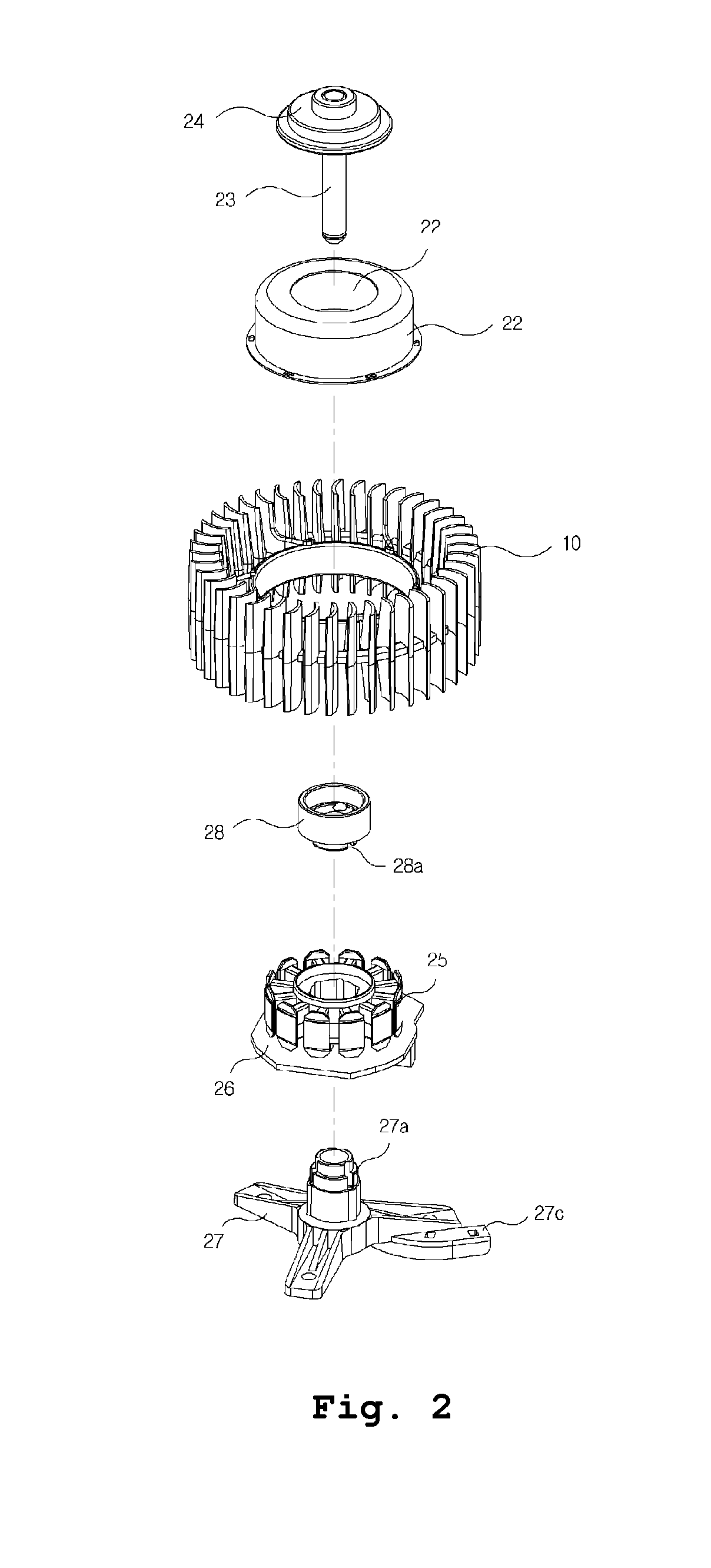
[0025]Hereinafter, a brushless direct current (BLDC) motor according to an exemplary embodiment of the present invention will now be described in detail with reference to FIGS. 2 to 10. FIG. 2 is an exploded perspective view illustrating a BLDC motor according to an embodiment of the present invention. FIG. 3 is an exploded cross-sectional view illustrating the BLDC motor of FIG. 2. FIG. 4 is a cross-sectional view illustrating the BLDC motor of FIG. 2. FIGS. 5 to 10 are views illustrating parts constituting the BLDC motor of FIG. 2.

[0026]A BLDC motor 20 for a hair dryer in accordance with the current embodiment includes: a rotor housing 22 having an accommodation space for accommodating a stator core 25, and including permanent magnets 21 on an inner surface thereof, and a shaft hole 22′ in the central portion thereof; a rotor frame 24 having an inner circumference integrally coupled to the upper end of a shaft 23 so as to rotate integrally with the shaft 23 coupled to the rotor ho...


PUM


Abstract

Provided is a BLDC motor for a hair dryer, which includes high strength plastic parts integrated through injection molding. Thus, the number of parts is decreased to thereby decrease manufacturing costs and the weight of the BLDC motor. Furthermore, a sirocco fan installed in the BLDC motor is directly coupled to an outer circumferential surface of a rotor housing so as to optimize an assembling structure of the sirocco fan, thereby stabilizing the rotation thereof. Accordingly, vibration and noise due to rotation can be reduced, and an amount of introduced air can be maximized. To this end, the BLDC motor includes a rotor housing including permanent magnets on an inner surface thereof, and a shaft hole in a central portion thereof to receive a shaft, wherein a sirocco fan for blowing air is coupled to an outer portion of the rotor housing, a rotor frame coupling the shaft to the rotor housing to integrally rotate them, a stator core around which a coil is wound to interact with a magnetic field formed on the permanent magnets, thereby generating torque, a PCB coupled to a lower portion of the stator core by a screw, a base bracket including a support protrusion on an upper outer portion thereof to support the stator core, and a bearing housing coupled to an upper portion of the base bracket to support a ball bearing, and including a removal prevention protrusion in a lower outer portion thereof to prevent removal of the stator core.

Description

TECHNICAL FIELD[0001]The present invention relates to a brushless direct current (BLDC) motor for a hair dryer, and a sirocco fan installed in the BLDC motor, and more particularly, to a BLDC motor for a hair dryer, which includes light weight inner parts partially integrated through injection molding, thereby entirely decreasing the weight thereof. Furthermore, a sirocco fan installed in the BLDC motor is directly coupled to an outer circumferential surface of a rotor housing so as to optimize an assembling structure of the sirocco fan, thereby stabilizing the rotation thereof. Accordingly, vibration and noise due to rotation can be reduced, and an amount of introduced air can be maximized.BACKGROUND ART[0002]Hair dryers, which are electric devices for drying an object, include a heater therein to heat air, and a fan motor for forcibly blowing the heated air, thereby conveniently drying a human hair or other wet objects. Thus, hair dryers are widely used for home and commercial pur...

Claims


Application Information

Patent Timeline
Patent Type & Authority Applications(United States)
IPC IPC(8): H02K9/04
CPCF04D25/0606H02K5/1735F04D25/062H02K7/14H02K15/12H02K5/08A45D20/12F04D25/064F04D25/0646H02K1/187H02K1/2786H02K1/2791
Inventor KWON, HYUK TAE
Owner JMW
Why Eureka
Try Eureka