Droplet discharging head and image forming apparatus

Active Publication Date: 2012-08-23
RICOH KK
View PDF3 Cites 33 Cited by
  • Summary
  • Abstract
  • Description
  • Claims
  • Application Information

AI Technical Summary

Benefits of technology

[0021]It is an object of the present invention to at least

Problems solved by technology

However, in miniaturizing the droplet discharging head, a simple use of the wire bonding method is insufficient and piezoelectric elements have to be highly densely arranged.
This causes problems in that wires may make contact with each other to cause shorting out of a circuit and reduction in production efficiency.
However, because of the above problems, the pitch between wires bonded by the wire bonding method cannot be decreased below about 60 μm, so that there is a limit in the miniaturization of the droplet discharging head.
This hinders improvement of production efficiency.
Due to the simultaneous operation of the piezoelectric elements,

Method used


Image

  • Droplet discharging head and image forming apparatus
  • Droplet discharging head and image forming apparatus
  • Droplet discharging head and image forming apparatus

Examples


first embodiment

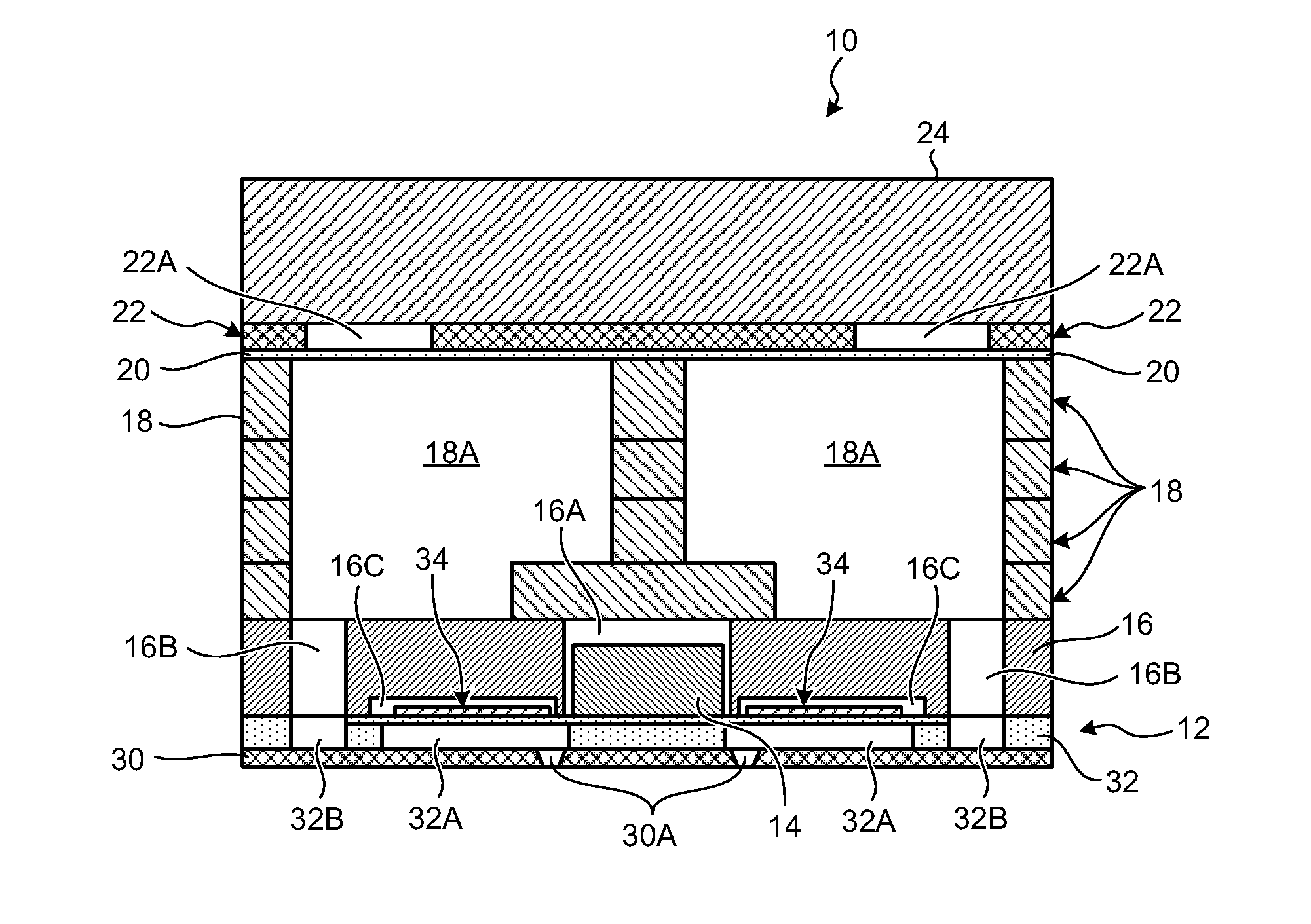
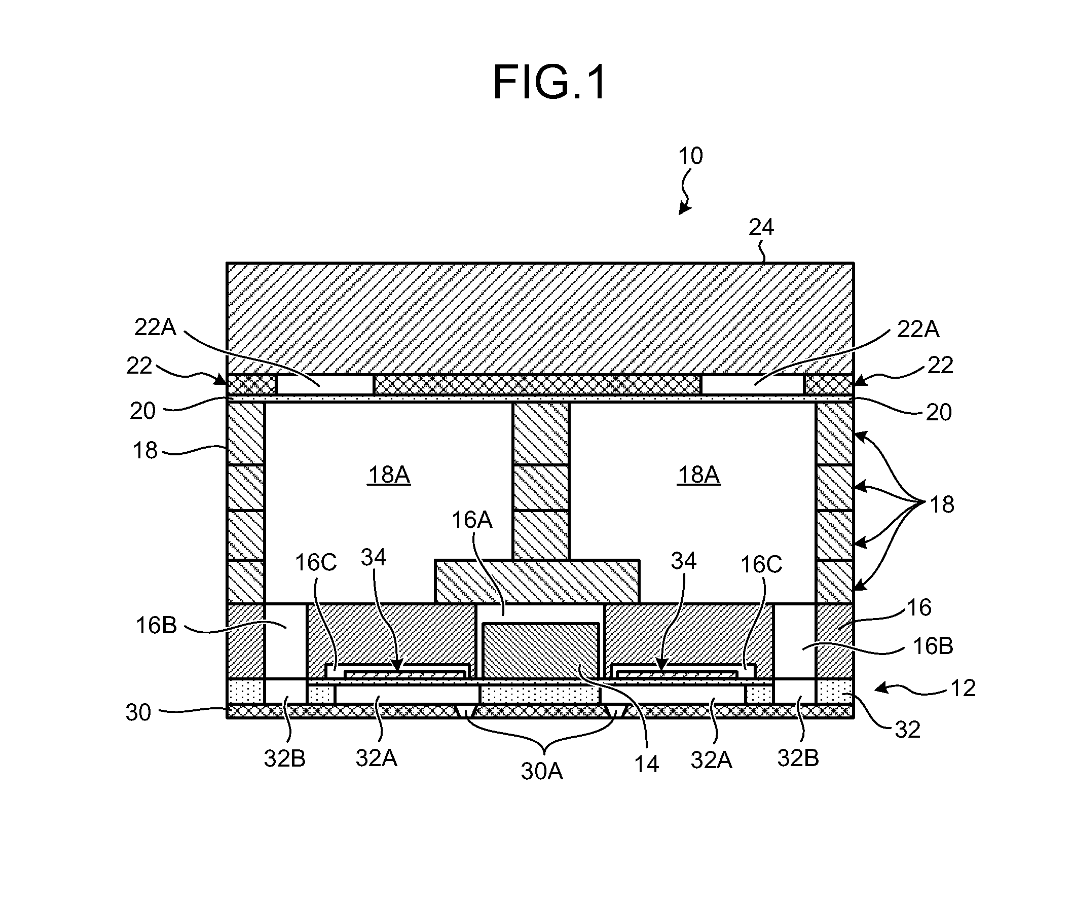
[0038]As illustrated in FIG. 1, a droplet discharging head 10 according to the embodiment includes a nozzle substrate 30, a liquid chamber substrate 12, a liquid supply substrate 16, a frame substrate 18, a cover plate 24, and a driving element 14. The driving element 14 is provided on the liquid chamber substrate 12 (to be described in detail later) in a flip-chip implementation.

[0039]The nozzle substrate 30 includes a plurality of nozzle openings 30A for discharging liquid droplets as illustrated in FIGS. 1 and 2. The nozzle openings 30A are through holes passing through the nozzle substrate 30 in the thickness direction, and are arranged across a surface of the nozzle substrate 30.

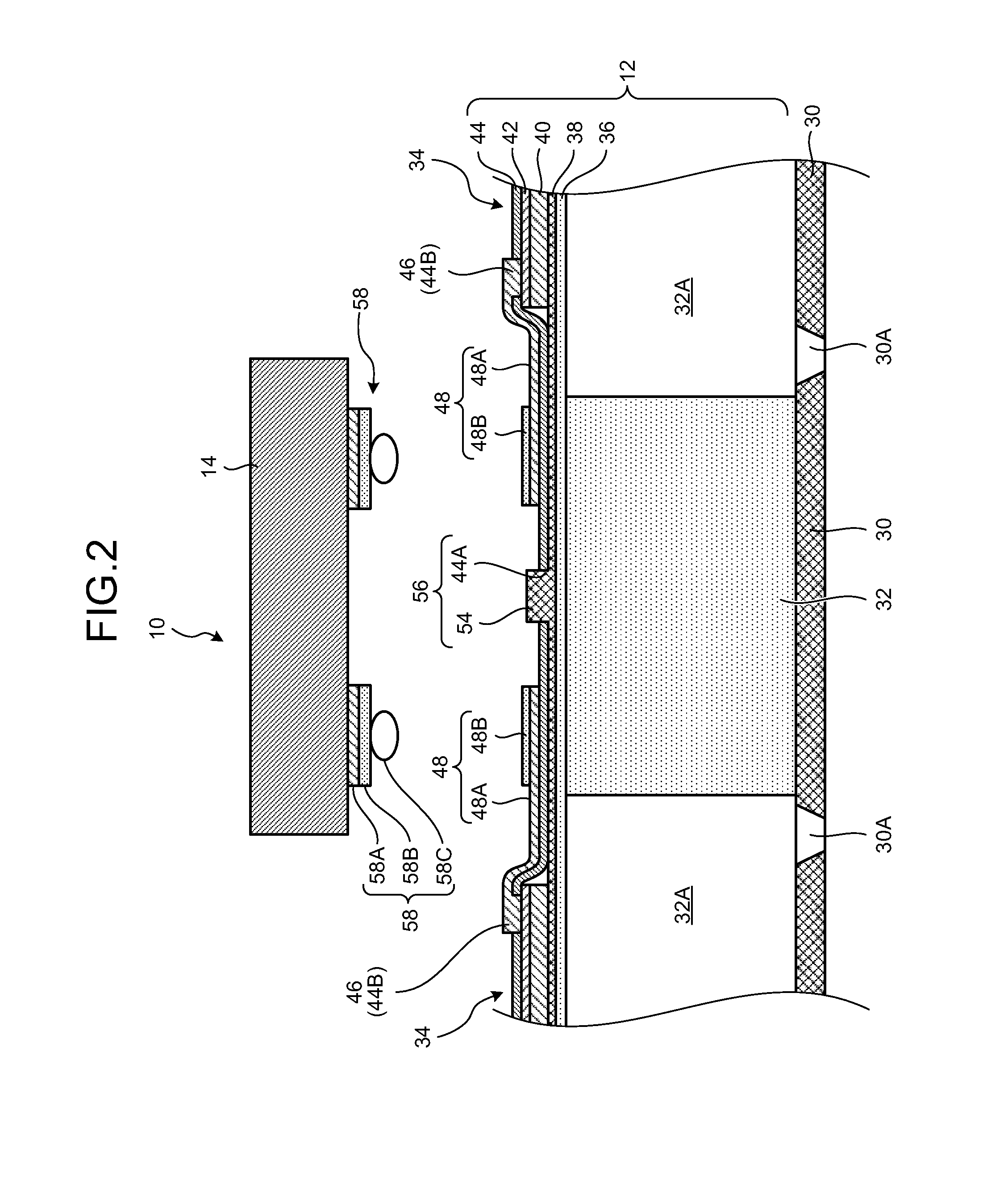
[0040]The liquid chamber substrate 12 includes, as illustrated in FIGS. 2 and 3, a flow path substrate 32, a vibration plate 36, a piezoelectric element 34, an insulating layer 44, an individual electrode 48, and a reinforcing wire 56 (first reinforcing wire).

[0041]The liquid supply substrate 16 is disp...

second embodiment

[0085]In the first embodiment described above, description has been given of a case where the first reinforcing wire 56 is bonded to the lower electrode 38 which is the common electrode of the piezoelectric element 34.

[0086]In the present embodiment, description will be given of a case where a wire corresponding to a first reinforcing wire 56 is electrically connected (bonded) to a voltage output terminal 58 for outputting the driving voltage signal to an individual electrode 48 connected to an upper electrode 42 that is an individual electrode provided in a piezoelectric element 34.

[0087]A droplet discharging head 10A according to the embodiment includes the nozzle substrate 30, a liquid chamber substrate 12A, the liquid supply substrate 16, the frame substrate 18, the cover plate 24, and a driving element 14A.

[0088]The liquid chamber substrate 12A includes, as illustrated in FIGS. 5 and 6, the flow path substrate 32, the vibration plate 36, the piezoelectric element 34, the insula...

third embodiment

[0108]In the first embodiment, the description has been given of a case where the first reinforcing wire 56 is provided and the first reinforcing wire 56 is bonded to the lower electrode 38 serving as a common electrode for the piezoelectric elements 34. In addition, in the second embodiment, the description has been given of a case where the voltage supply electrode 50 is provided and the voltage supply electrode 50 is connected to the voltage output terminal 58.

[0109]Meanwhile, according to the present embodiment, description will be given of a configuration that includes both the first reinforcing wire 56 of the first embodiment and the voltage supply electrode 50 of the second embodiment.

[0110]A droplet discharging head 10B of the embodiment includes a nozzle substrate 30, a liquid chamber substrate 12B, a liquid supply substrate 16, a frame substrate 18, a cover plate 24, and a driving element 14B.

[0111]As illustrated in FIGS. 7 and 8, the liquid chamber substrate 12B includes ...


PUM


Abstract

A droplet discharging head includes: a nozzle substrate that includes a nozzle opening to discharge a droplet therethrough; a liquid chamber substrate that includes liquid pressure chambers communicating with the nozzle openings; a vibration plate arranged to face the nozzle substrate with the liquid chamber substrate interposed therebetween; piezoelectric elements that are provided to face the liquid pressure chambers with the vibration plate interposed therebetween and are arranged in a predetermined direction; a driving element provided, in a flip-chip implementation, on a flow path substrate that includes the nozzle substrate, the liquid chamber substrate, the vibration plate, and the piezoelectric elements; and a first reinforcing wire that is disposed to at least one of the flow path substrate and the driving element, has a band shape extending in a direction along a row of the piezoelectric elements, and is connected to a common electrode shared by the piezoelectric elements.

Description

CROSS-REFERENCE TO RELATED APPLICATIONS[0001]The present application claims priority to and incorporates by reference the entire contents of Japanese Patent Application No. 2011-033850 filed in Japan on Feb. 18, 2011.BACKGROUND OF THE INVENTION[0002]1. Field of the Invention[0003]The present invention relates to a droplet discharging head and an image forming apparatus.[0004]2. Description of the Related Art[0005]An image forming apparatus such as an inkjet recording apparatus has various advantages such as high image quality, flexibility in coping with high speed printing, easy selection of ink types, usability of inexpensive plain sheets, and the like. Among the image forming apparatuses, a so-called “ink-on-demand type” droplet discharging device has been in wide use for the capability of discharging ink droplets only when the ink is needed because collection of ink droplets unnecessary for recording is not required.[0006]As a droplet discharging head used in the droplet discharg...

Claims


Application Information

Patent Timeline
IPC IPC(8): B41J2/045
CPCB41J2/055B41J2/14233B41J2/161B41J2/1623B41J2/14201B41J2002/14241B41J2002/14491B41J2/04541B41J2/04581B41J2/1646
Inventor TAKEMOTO, TAKESHIKIDA, HITOSHI
Owner RICOH KK
Why Eureka
Try Eureka