Digital demodulation of pulse-width modulated signals

a digital demodulation and pulse-width technology, applied in the field of digital demodulation, can solve the problems of not being easily scalable with respect to the frequency of the pwm signal, complex approach in terms of design effort and circuit layout,

Active Publication Date: 2012-08-23
TEXAS INSTR INC
View PDF3 Cites 24 Cited by
  • Summary
  • Abstract
  • Description
  • Claims
  • Application Information

AI Technical Summary

Problems solved by technology

However, such an approach may be complex in terms of design effort and circuit layout, and may not be easily scalable with respect to frequency of the PWM signal.
Such an approach may not be desirable at least due to the need for a very high frequency clock (e.g., of the order of GigaHertz).

Method used


Image

  • Digital demodulation of pulse-width modulated signals
  • Digital demodulation of pulse-width modulated signals
  • Digital demodulation of pulse-width modulated signals

Examples


Embodiment Construction

[0021]Various embodiments are described below with several examples for illustration.

[0022]1. Example Environment

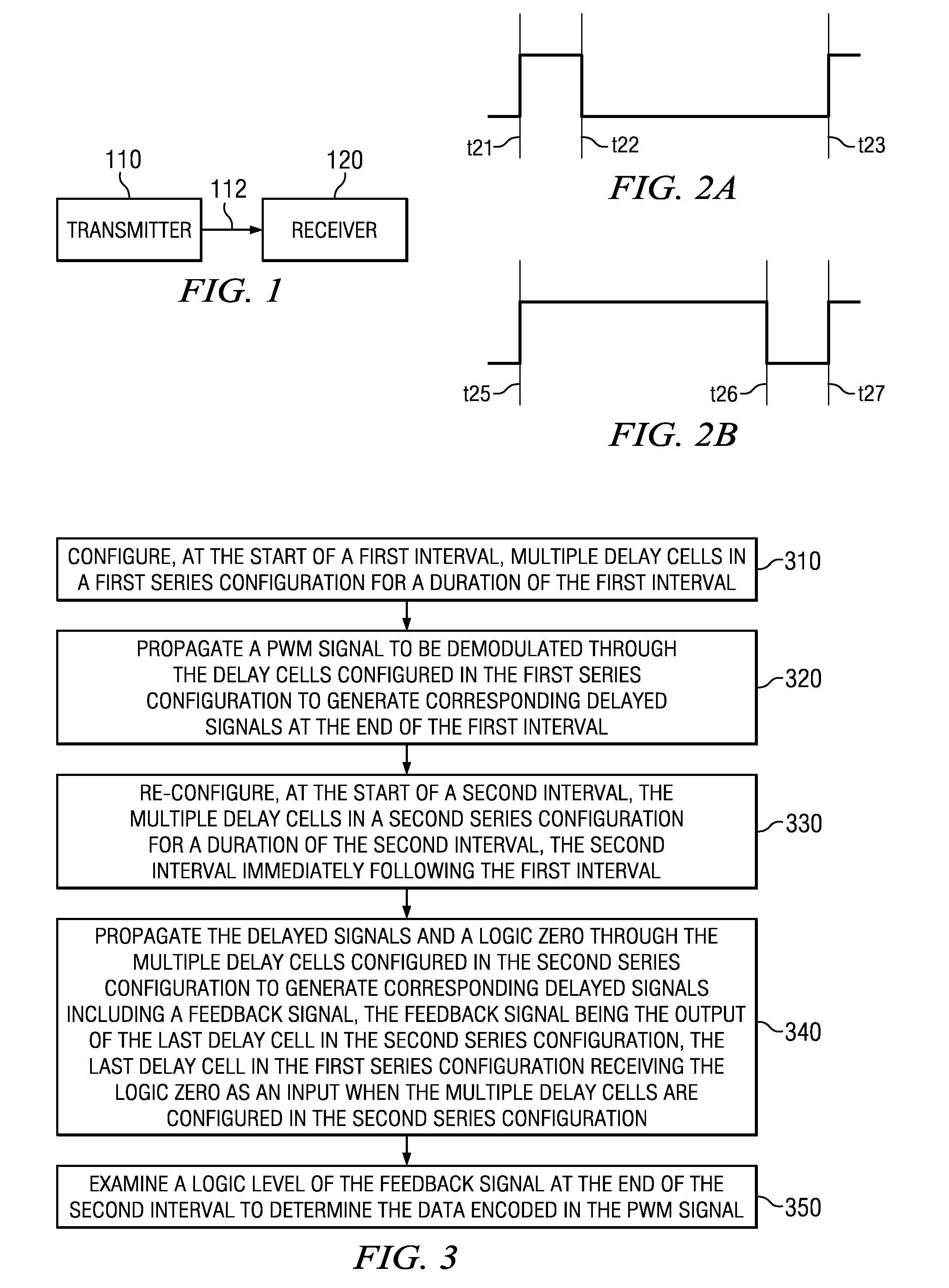
[0023]FIG. 1 is a block diagram illustrating the details of an example environment in which several embodiments can be implemented. FIG. 1 is shown containing transmitter 110 and receiver 120. In an embodiment, each of transmitter 110 and receiver 120 is designed to operate according to M-PHY (mobile interfaces standard) or USB3 protocol. However, transmitter 110 and receiver 120 may in general operate consistent with any other standard that uses pulse width modulation (PWM). Transmitter 110 transmits PWM signals to receiver 120 on path 112. Receiver 120 demodulates the PWM signals to extract the corresponding data values.

[0024]While the description below is provided with respect to demodulation of a single period of a PWM signal, it may be appreciated that the demodulation technique(s) can be extended without limit to demodulate each of multiple periods of the PWM signal...


PUM


Abstract

A digital PWM demodulator includes a first set of delay cells to receive a PWM signal and to propagate the PWM signal in a forward direction for a first interval. Delayed signals obtained at the end of the first interval are propagated in the reverse direction through the delay cells for a second interval. A logic zero feeds into the last cell at the start of the second interval. The output of a last cell in the delay cells at the end of the second interval is indicative of a data value modulated on the PWM signal. The digital PWM demodulator includes a second set of delay cells designed to operate identical to the first set of delay cells. The first set of delay cells and the second set of delay cells in conjunction with additional digital circuitry demodulate alternate periods of the PWM signal.

Description

BACKGROUND[0001]1. Technical Field[0002]Embodiments of the present disclosure relate generally to digital demodulation, and more specifically to digital demodulation of pulse-width modulated signals.[0003]2. Related Art[0004]Pulse width modulation (PWM) refers to a modulation technique in which data / information is embedded in (or represented by) the duty cycle of a signal. Successive periods of the signal may be concatenated to form a continuous stream of periods, with the duty cycle of each period representing corresponding data / information. The ratio of the ON (or high) duration of the signal to the period of the signal is termed duty cycle. A duty cycle of 50% corresponds to a situation when the ON and OFF durations of the signal are equal. Assuming the data modulated on the PWM signal is binary, a duty cycle less than 50% may be used to represent one value of the (binary) data, while a duty cycle greater than 50% may be used represent the other value of the data.[0005]Digital de...

Claims


Application Information

Patent Timeline
Patent Type & Authority Applications(United States)
IPC IPC(8): H04L27/06
CPCH04L25/4902
Inventor SUBBURAJ, KARTHIKKAMATH, ANANT SHANKARJANARDHANAN, JAYAWARDAN
Owner TEXAS INSTR INC
Why Eureka
Try Eureka