
Process for fabricating continuously coated electrodes on a porous current collector and cell designs incorporating said electrodes

a current collector and electrode active material technology, applied in the field of electrochemical cells, can solve the problems of insufficient cohesion of electrode active materials, difficulty in continuously coating electrode active materials to current collector screens, and low energy density of cells

Inactive Publication Date: 2002-09-19
WILSON GREATBATCH LTD
View PDF19 Cites 30 Cited by
  • Summary
  • Abstract
  • Description
  • Claims
  • Application Information

AI Technical Summary

Problems solved by technology

The problem is that it is difficult to continuously coat an electrode active material to a current collector screen.
This is labor-intensive, particularly if the cell being produced requires substantial electrode surface area.
Less than 3 weight percent of the binder provides insufficient cohesiveness to the loosely agglomerated electrode active materials to prevent delamination, sloughing and cracking during electrode preparation and cell fabrication and during cell discharge.
The greater the amount of aluminum present by weight in the alloy, however, the lower the energy density of the cell.
Less than 20% by weight of PVDF results in insufficient cohesion of the electrode active material during electrode fabrication and cell assembly, and during charge / discharge cycling.
This approach is compromised by problems associated with handling lithiated carbon outside of the cell.
Lithiated carbon tends to react with explosive results when contacted by air.
For one, compaction of an active material to an un-perforated foil tends to cause curling.
This condition creates a material imbalance between both sides of the electrode.

Method used


Image

  • Process for fabricating continuously coated electrodes on a porous current collector and cell designs incorporating said electrodes
  • Process for fabricating continuously coated electrodes on a porous current collector and cell designs incorporating said electrodes
  • Process for fabricating continuously coated electrodes on a porous current collector and cell designs incorporating said electrodes

Examples


Embodiment Construction

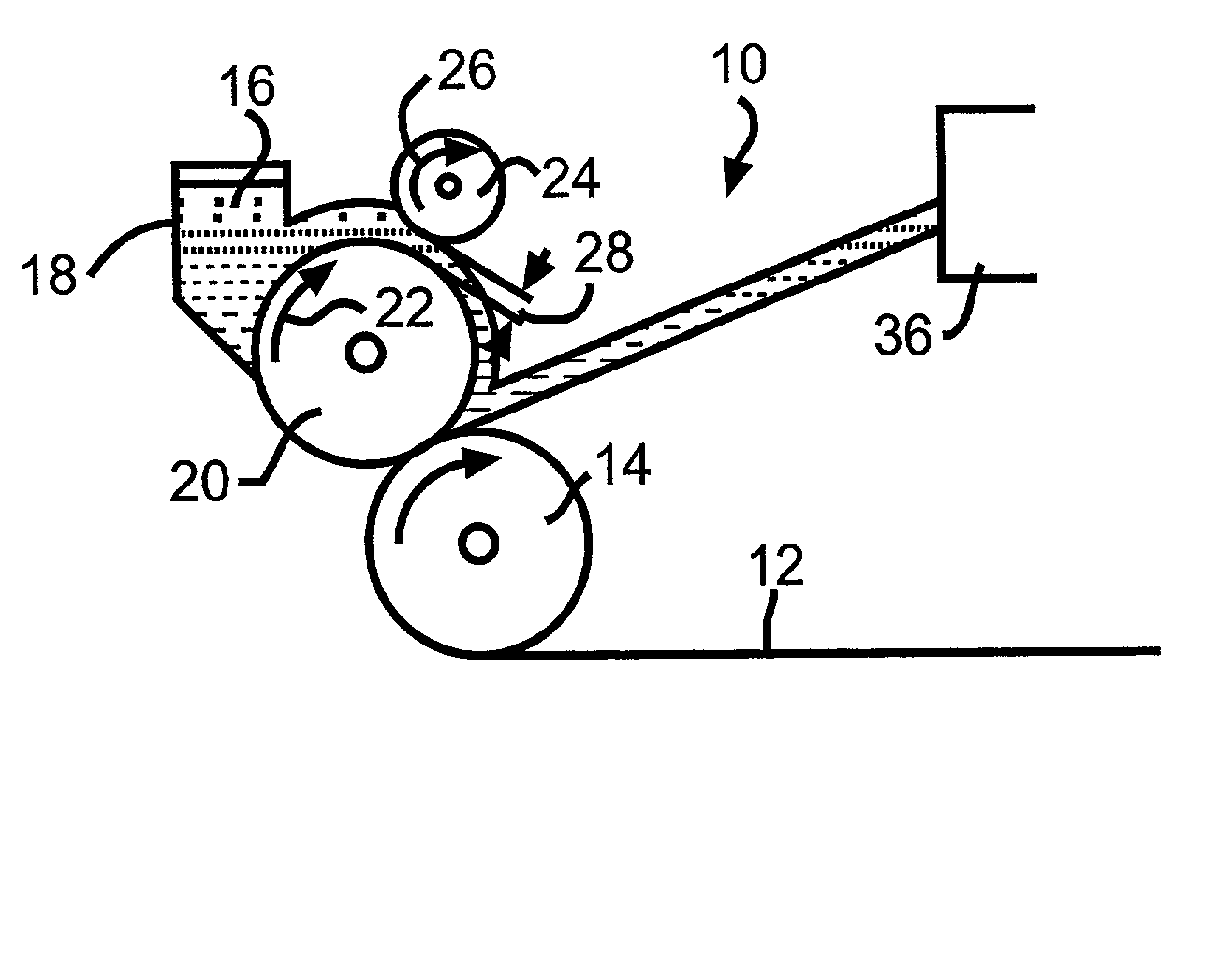
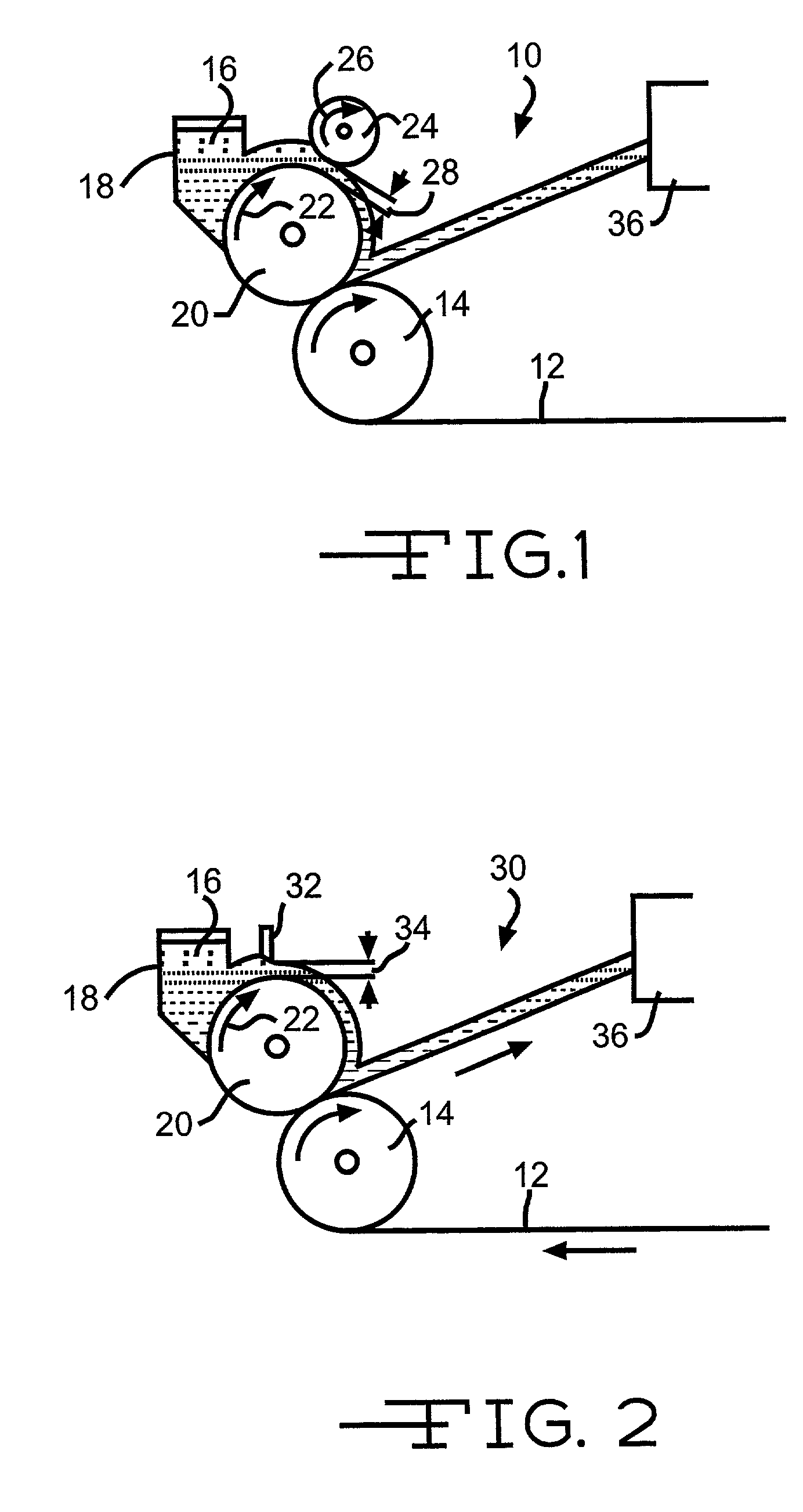
[0058] A mixture of 92.0 grams of graphite and 8.0 grams of polyvinylidene fluroide binder in N-methyl pyrrolidinone was mixed to provide a slurry. The slurry was horizontally coated onto a copper foil containing 5% openings by the knife-over-roll method. The openings were 0.002" in diameter. A piece of foil without openings was placed under the perforated foil being coated and both foils were passed through a drying oven set to 245.degree. C. The electrodes obtained were cut to cell size, compacted and folded such that the uncoated side of the foil was back-to-back.

[0059] A mixture of 91.0 grams of LiCoO.sub.2, 3.0 grams of polyvinylidene fluoride, and 6.0 grams of graphite was mixed with N-methyl pyrrolidinone to provide a slurry. The slurry was coated onto an aluminum foil containing 5% openings by the knife-over-roll method. The openings were 0.002" in diameter. A piece of foil without openings was placed under the foil being coated and both foils were passed through a drying ov...


PUM

PropertyMeasurementUnit
Fractionaaaaaaaaaa
Fractionaaaaaaaaaa
Timeaaaaaaaaaa

Abstract

The invention is directed to an electrochemical cell having at least one of its electrodes produced by coating a slurry mixture of an active material, possibly a conductive additive, and a binder dispersed in a solvent and contacted to a perforated current collector foil. It is particularly important that the active slurry does not move through the perforations of the current collector. For this reason, a barrier is placed against the opposite side of the current collector to block the perforations as the current collector is being coated with the slurry. After volatilizing the solvent, a second, different active material is coated to the opposite side of the current collector, either as a slurry, a pressed powder, a pellet or a free standing sheet. An example of this is a cathode having a configuration of: SVO / current collector CFx. The opposed active materials on the current collector can also be of the same chemistry.

Description

[0001] The present application claims priority from provisional application Serial No. 60 / 276,098, filed Mar. 15, 2001.[0002] 1. Field of the Invention[0003] The present invention generally relates to the conversion of chemical energy to electrical energy. More particularly, the present invention is directed to an electrochemical cell in which the current collector for at least one of the electrodes is of a metal foil containing openings or perforations that provide for ion migration from one side of the foil to the other. The openings may comprise 2% to 80% of the current collector surface area.[0004] The perforated conductive foil is particularly useful for fabricating electrodes, whether of a positive or negative polarity for a primary or a secondary cell, from an electrode active material slurry. The active slurry is continuously coated onto one side of the current collector by applying a barrier to the opposite side of the foil. The barrier allows the slurry to fill the opening...

Claims


Application Information

Patent Timeline
IPC IPC(8): H01M4/139H01M4/1391H01M4/1393H01M4/36H01M4/58H01M4/74H01M6/10H01M6/16H01M10/0587
CPCH01M4/04H01M4/0404H01M4/0409H01M4/0416H01M4/139H01M4/1391H01M4/1393H01M4/362H01M4/366H01M4/5825H01M4/5835H01M4/742H01M6/10H01M6/16H01M10/0587Y02E60/122Y10T29/49115Y02E60/10Y02P70/50
Inventor GAN, HONGTAKEUCHI, ESTHER S.RUBINO, ROBERT S.
Owner WILSON GREATBATCH LTD
Learn More