
Devices and method for wear estimation based memory management

a technology of memory management and wear estimation, applied in the field of wear estimation based memory management devices and methods, can solve the problems of unfitting voltage threshold distribution lobes with very narrow voltage threshold distribution lobes, and unsatisfactory performance of flash memory cells

Active Publication Date: 2012-08-23
AVAGO TECH INT SALES PTE LTD
View PDF5 Cites 86 Cited by
  • Summary
  • Abstract
  • Description
  • Claims
  • Application Information

AI Technical Summary

Benefits of technology

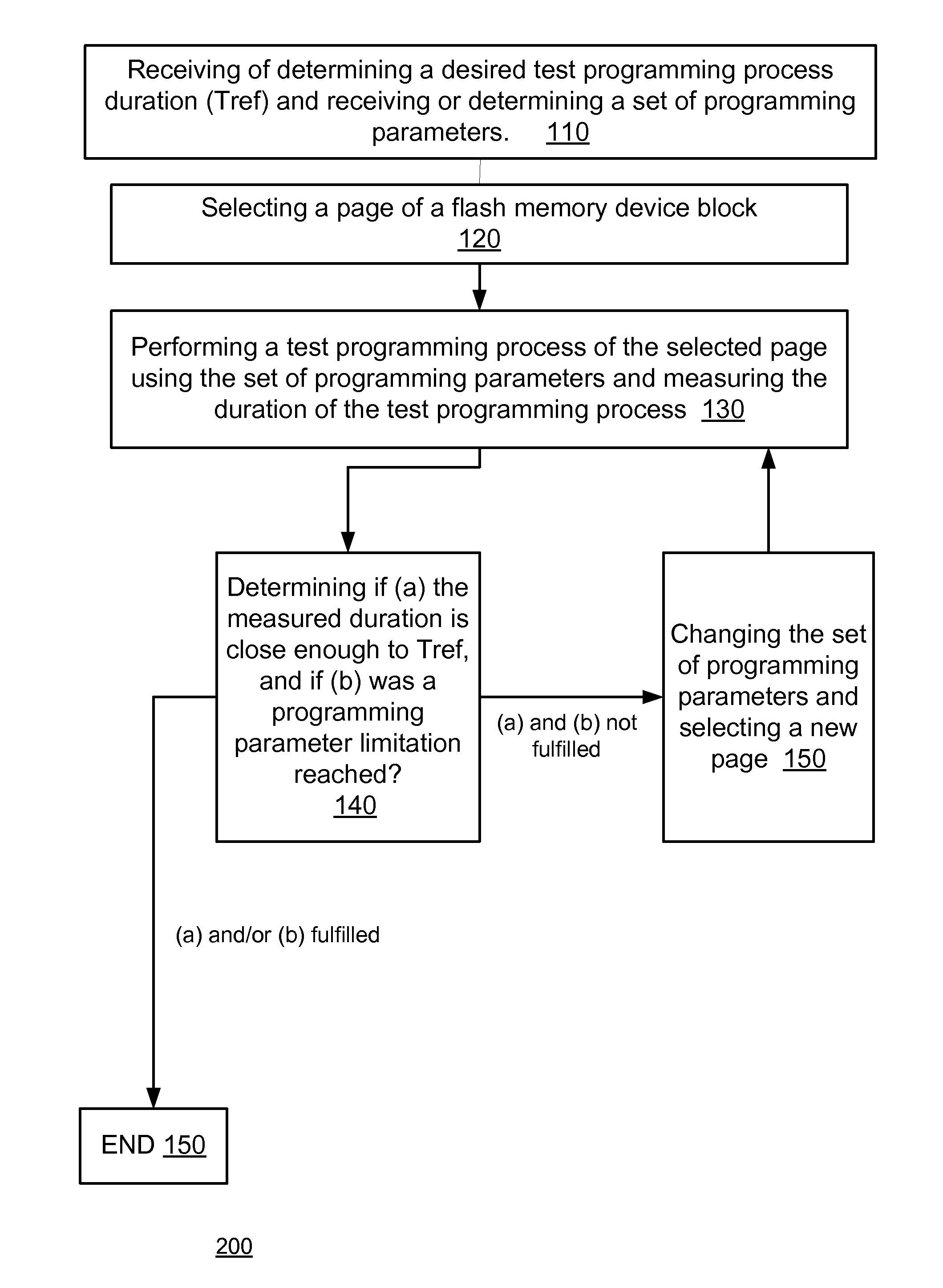
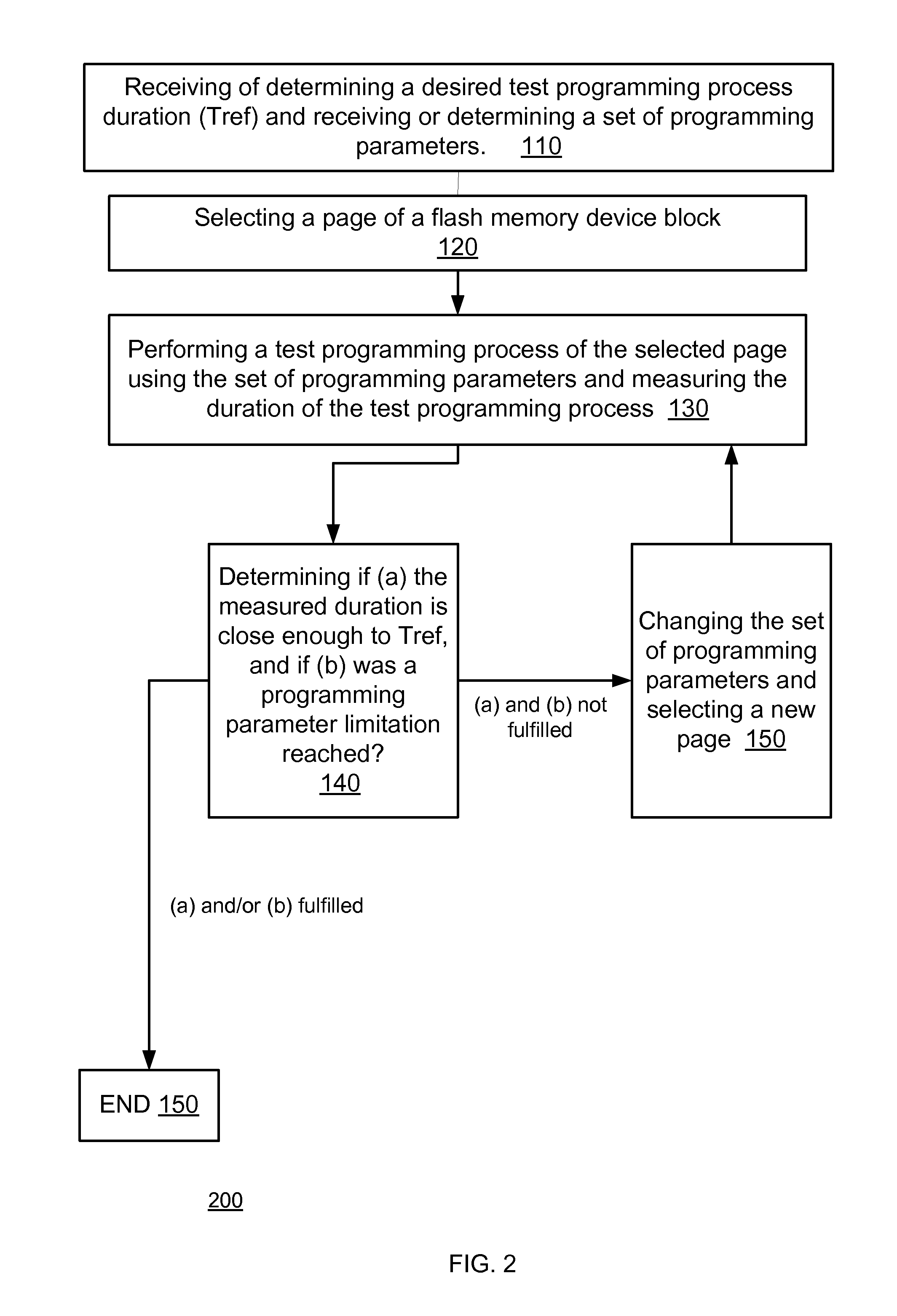
The present invention provides a method for estimating the wear characteristic of a flash memory device by programming information to a specific portion of the device and measuring the duration of the programming process. The method can be triggered by various events such as read errors, program and erase cycles, and the evaluation of wear levels in other portions of the device. The method can also involve programming non-test information while using different programming parameters and allocating portions of the device for programming based upon the estimated wear characteristic. The method can also involve performing multiple sets of test programming processes and measuring the durations of the processes to provide a time to wear mapping. The invention also includes a computer readable medium that stores instructions for performing the method.

Problems solved by technology

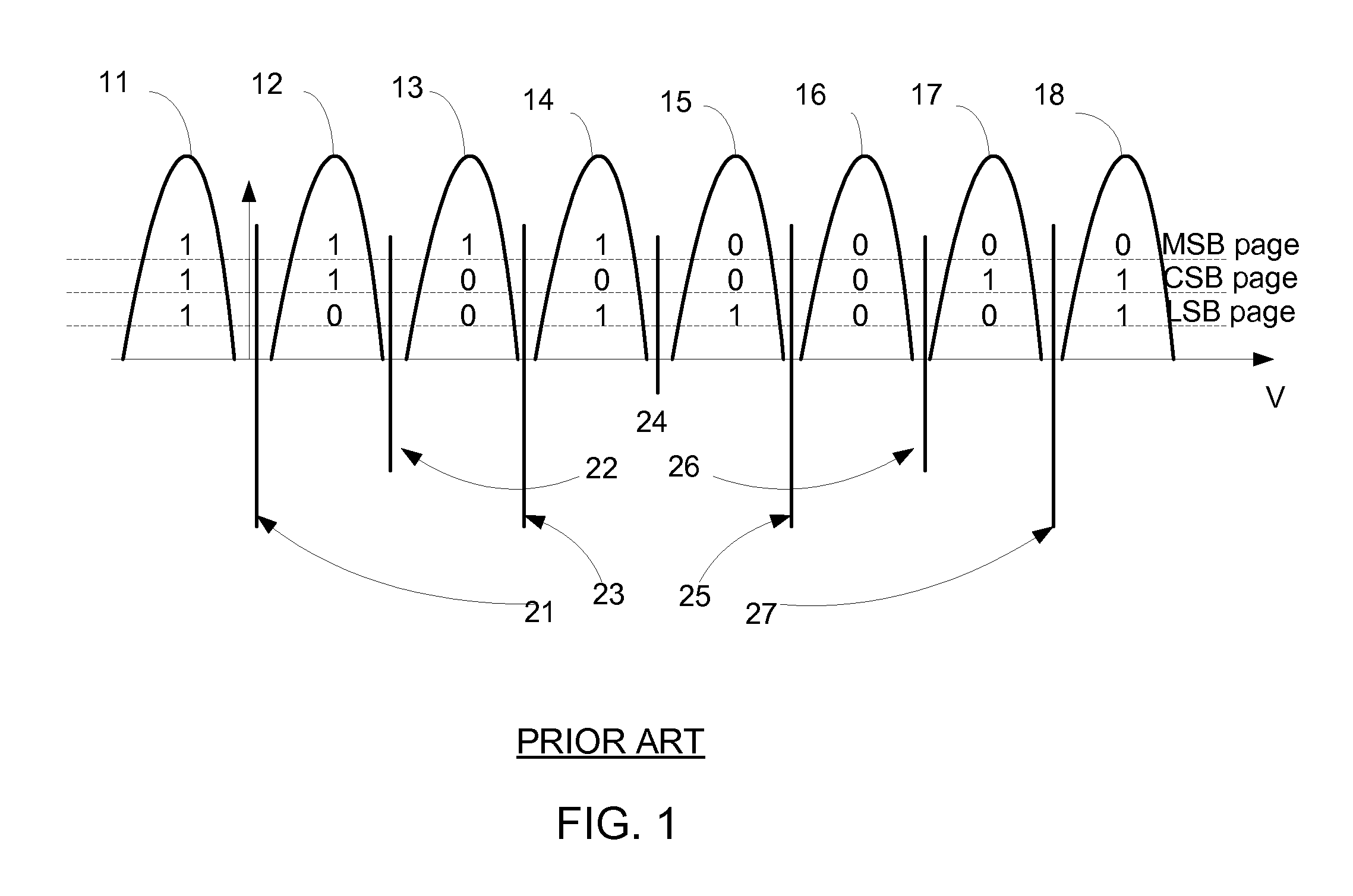
If, after the maximal number of pulses is used, there remain cells that did not pass the verify test (were not programmed to the desired programming voltage), a program error (or failure) can be declared.
Thus, higher Vstep and Vstart can assist in speeding up the programming process but may not be fitted to provide very narrow voltage threshold distribution lobes.
The programming and erasing of flash memory cells cause unwanted charges to be trapped in the flash memory cells.
These charges can introduce errors in the programming and reading processes.

Method used


Image

  • Devices and method for wear estimation based memory management
  • Devices and method for wear estimation based memory management
  • Devices and method for wear estimation based memory management

Examples


Embodiment Construction

[0058]In the following detailed description, numerous specific details are set forth in order to provide a thorough understanding of the invention. However, it will be understood by those skilled in the art that the present invention may be practiced without these specific details. In other instances, well-known methods, procedures, and components have not been described in detail so as not to obscure the present invention.

[0059]The subject matter regarded as the invention is particularly pointed out and distinctly claimed in the concluding portion of the specification. The invention, however, both as to organization and method of operation, together with objects, features, and advantages thereof, may best be understood by reference to the following detailed description when read with the accompanying drawings.

[0060]It will be appreciated that for simplicity and clarity of illustration, elements shown in the figures have not necessarily been drawn to scale. For example, the dimensio...


PUM


Abstract

A system, a non-transitory computer readable medium and a method for wear estimation of a flash memory device, the method may include: programming information to a first portion of the flash memory device during a test programming process; measuring a duration of the test programming process; and estimating a wear characteristic of the first portion of the flash memory device thereby providing an estimated wear characteristic, wherein the estimating is responsive to the duration of the test programming process.

Description

RELATED APPLICATIONS[0001]This application is a NONPROVISIONAL of, claims priority to and incorporates by reference U.S. provisional patent application No. 61 / 445,729, filing date Feb. 23, 2011 which is incorporated herein by reference.BACKGROUND OF THE INVENTION[0002]A NAND flash memory array includes rows and columns (strings) of cells. A cell may include a transistor. During a read operation, an entire row / page of the NAND flash memory array is read. This is done by applying a bias voltage to all rows not being read and a reference threshold voltage to the row that should be read.[0003]The bias voltage allows the transistor of the NAND flash memory array to fully conduct. The cells lying on the row being read will conduct only if the threshold voltage is sufficiently high to overcome the trapped charge in the floating gate.[0004]A sense amplifier is connected to each string which measures the current through the string and outputs either a “1” or a “0” depending whether the curre...

Claims


Application Information

Patent Timeline
Patent Type & Authority Applications(United States)
IPC IPC(8): G11C29/08G06F11/26
CPCG11C11/56G11C16/00G11C2029/5002G11C29/028G11C29/50004G11C16/349
Inventor WEINGARTEN, HANANSTEINER, AVI
Owner AVAGO TECH INT SALES PTE LTD
Learn More