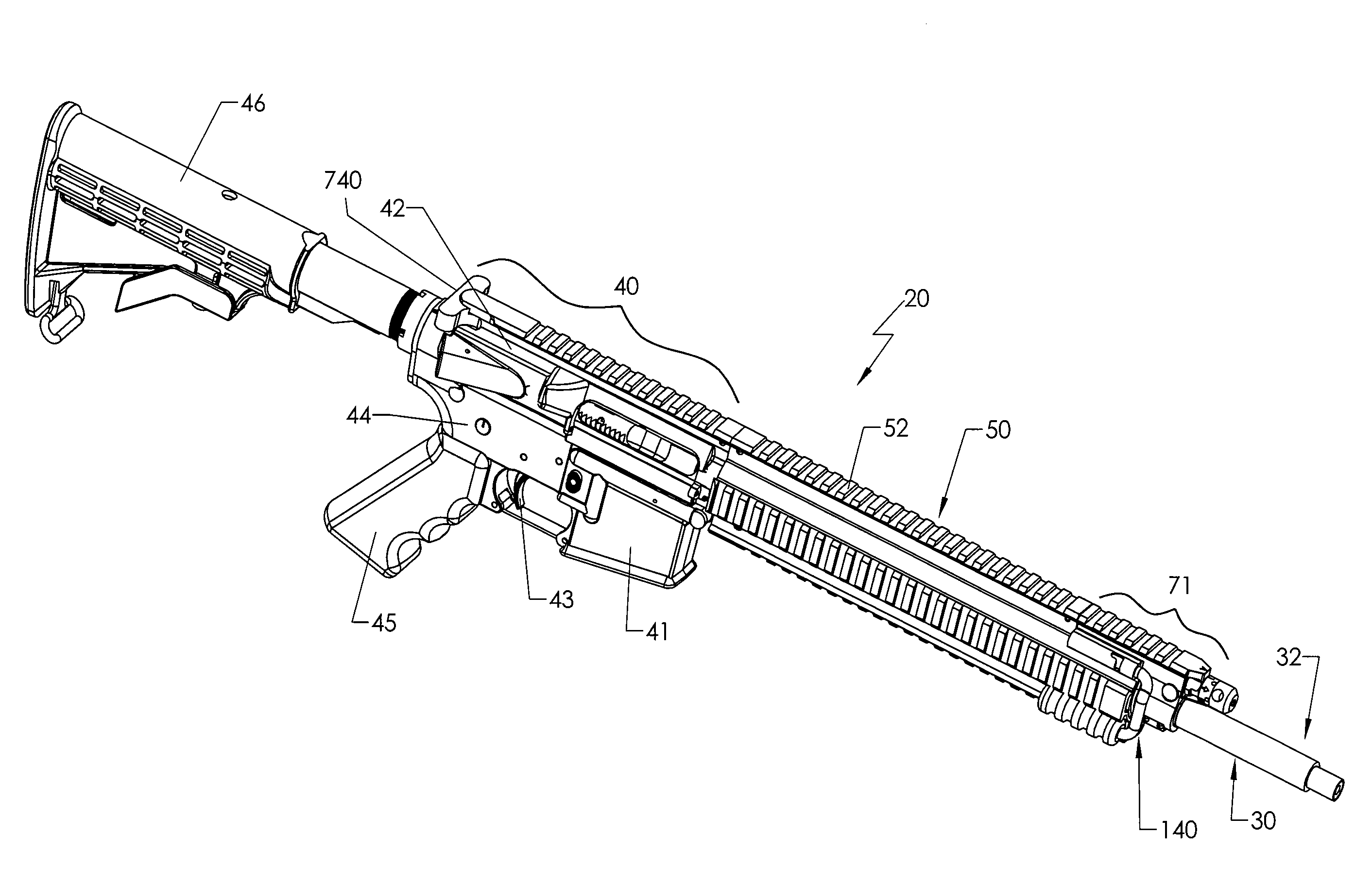
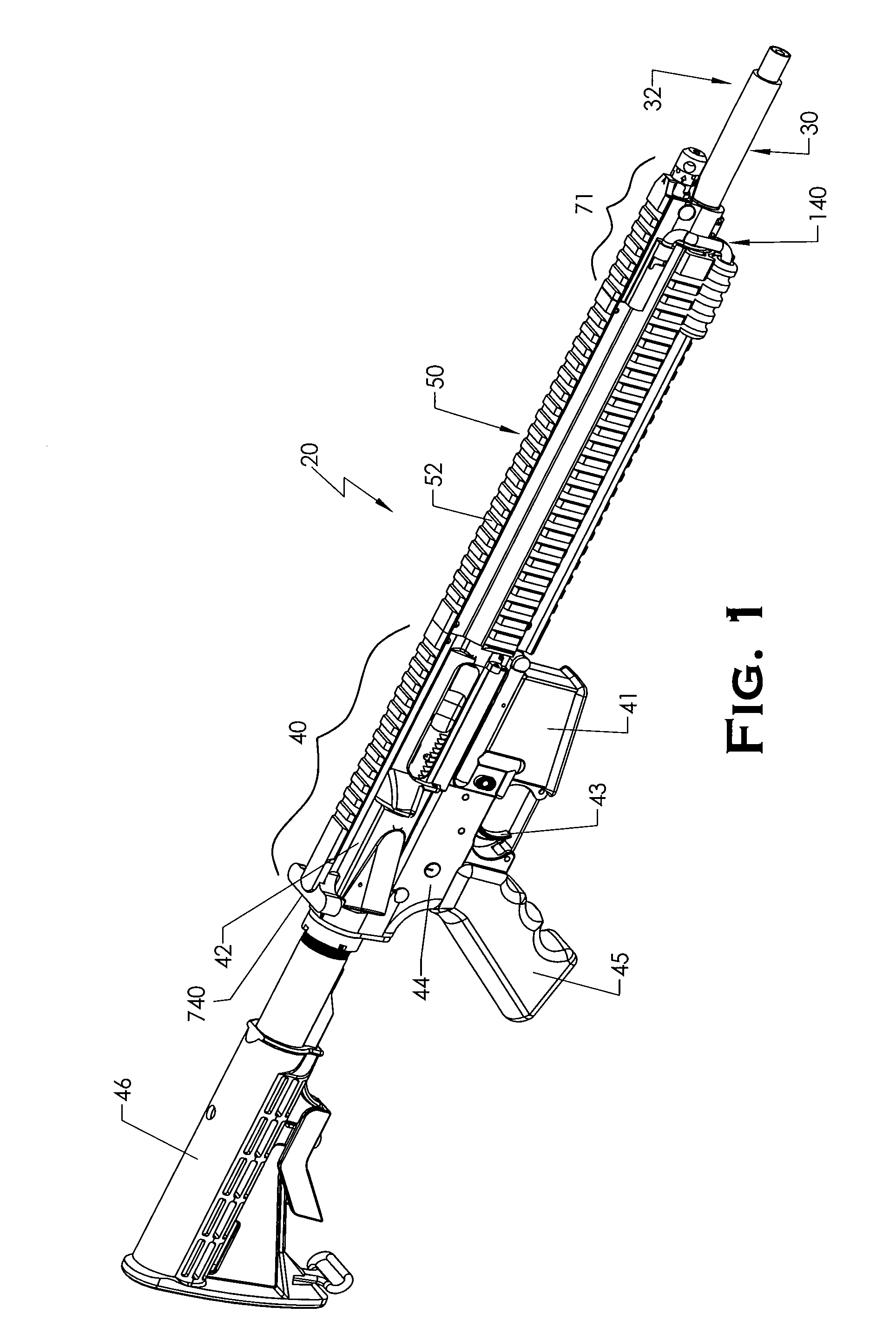
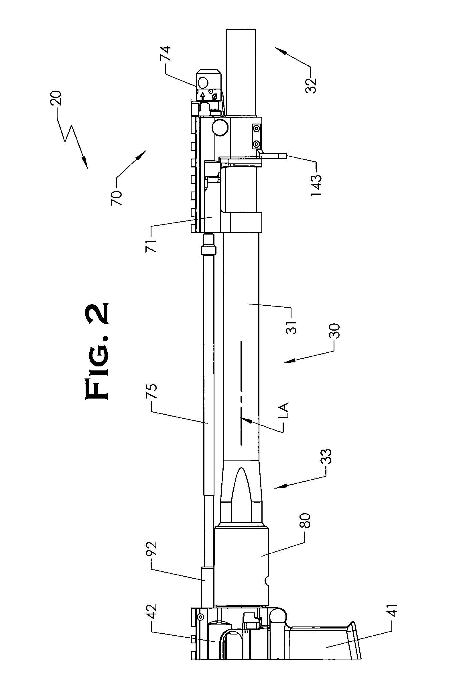
[0007]The present invention provides a firearm with a quick-change barrel retaining system suitable for use in rifles and other firearms. In a preferred embodiment, the barrel is secured to the
rifle by a locking member such as a barrel nut which preferably is attached to receiver. Although in one embodiment the barrel nut may be similarly threaded onto the receiver assembly like a conventional barrel nut in the usual manner, the barrel nut according to the present invention is configured and adapted to accomplish the barrel locking function in a different manner. Unlike known barrel nuts described heretofore that secure the barrel to the receiver by
trapping an annular barrel
flange between the barrel nut and receiver, the present barrel nut in a preferred embodiment is specially configured to directly engage the
rifle barrel such that a locking relationship is formed between the barrel nut and barrel independently of the receiver. Advantageously, unlike known prior barrel nuts, the present barrel nut does not require removal or other manual manipulation by a user in order to remove the barrel from the
rifle, but rather acts as a replaceable extension of the receiver. The present barrel nut may remain attached to the receiver assembly and stationary in position when a barrel is removed or installed, as will be further described herein. Advantageously, this allows the barrel to be quickly changed without tools while retaining the originally
set point of aim for the new barrel because the barrel nut remains fixed to the firearm. Therefore, each new barrel need not be re-sighted after installation which is particularly important during field combat conditions. Also advantageously, the handguard and components supported by or mounted to the handguard also do not require partial disassembly or removal in order to replace the barrel. Preferably, the barrel retaining system does not require the use of any separate tools to remove the barrel from the firearm.
[0008]In some preferred embodiments, a barrel retaining system according to principles of the present invention provides a releasable dual
locking mechanism intended to improve the tightness and reliability of the
coupling between the barrel and rifle. The barrel retaining system reduces or eliminates possible vibration / rattling when the rifle is discharged. In some embodiments, an additional third
locking mechanism may be provided to further enhance a secure locking relationship between the barrel and rifle. In one embodiment, the three locking mechanisms detachably lock the barrel to the rifle at three different axial locking locations for improved tightness. In one embodiment, one
locking mechanism may be provided by barrel locking lugs formed on a barrel assembly that mate with corresponding locking elements such as splines formed on a barrel nut. A second locking mechanism may be provided by engagement between a
flange on the barrel assembly with the barrel nut splines. A third locking mechanism may be provided by frictional engagement between a tapered contact surface on the barrel assembly with the barrel nut splines. The foregoing locking mechanisms and associated structures are further described herein.
[0016]The spring member advantageously at least partially alleviates some of the stringent manufacturing tolerances that may be otherwise necessary and reduces the tolerance stack between the barrel nut and barrel assembly, as further described herein. This translates into simpler and less costly fabrication of components used in the barrel system by reducing and / or eliminating
machining operations. In addition, reduction in the tolerance stack promotes more reliable meshing of inter-fitting parts by eliminating some of the potential dimensional variations possible due to manufacturing tolerance or service factors such as heat and pressure.
[0020]A method for mounting a spring-loaded quick coupling barrel assembly to a firearm is also provided. In one embodiment, a method for removably mounting a spring-loaded quick coupling barrel assembly to a firearm includes: providing a receiver with an axially movable bolt and a barrel nut coupled to the receiver inserting a rearward portion of a barrel assembly axially into the barrel nut, the rearward portion of the barrel assembly defining a chamber at a rearward breech end for holding a
cartridge and an opposing forward
muzzle end; compressing a spring member against the barrel nut with the barrel assembly; rotating the barrel assembly in a first rotational direction; and lockingly engaging the barrel assembly with the barrel nut in a locked position, wherein the barrel assembly cannot be axially removed from the barrel nut. In one embodiment, the compressing step may include compressing the spring member against a lock nut rotatably disposed on the barrel assembly. In one embodiment, the method includes axially biasing the barrel assembly forward away from to barrel nut with the spring member. In one embodiment, the lockingly engaging step includes positioning barrel locking lugs disposed on the barrel assembly behind splines disposed on the barrel nut, the splines preventing axial removal of the barrel assembly from the barrel nut when the barrel assembly is in the locked position. The spring member operates to maintain tight engagement between the barrel locking lugs and splines.
[0030]According to another aspect of the present invention, a barrel interlock system is provided that is operative to prevent removal of a rotary operated quick coupling barrel assembly such as those described herein from a firearm when the breech is closed (i.e. bolt is engaged with rear of chamber). This interlock system is intended to prevent the unsupported
discharge of ammunition (i.e.
cartridge) by forming a rotationally meshed relationship between the bolt carrier and barrel assembly such that the barrel assembly is not rotatable and therefore not removable from the firearm when in a locked position coupled to the receiver.


