Enhanced imaging method and apparatus

a technology of enhanced imaging and surface characteristics, applied in the field of enhanced imaging methods and apparatuses, can solve problems such as unrealistic images, and achieve the effects of accurate portrayal of aberrant areas, high quality, and high quality

Active Publication Date: 2012-08-30
HERMARY OPTO ELECTRONICS
View PDF11 Cites 36 Cited by
  • Summary
  • Abstract
  • Description
  • Claims
  • Application Information

AI Technical Summary

Benefits of technology

[0014]The present invention provides for accurate, high quality images of the objects scanned by processing raw image linear scans (“Raw Scans”), which can be assembled sequentially to form raw images (“Raw Images”). The Raw Scans are acquired from separate cameras simultaneously. The cameras may be CCD, CMOS linear sensors, or use other photo-sensitive devices that responds to varying levels of light emanating from its field of view. Processing the Raw Scans as summarized below to address distortions, and combining the resulting processed images is done in order to arrive at the desired high quality Enhanced Image, void of specular reflections, with uniformity of image where the object scanned has uniformity of surface, and accurate portrayal of aberrant areas where the object scanned has such aberrations.

Problems solved by technology

Unrealistic image results, apart from the effects of specular reflection, are mainly due to radiation geometric pattern variance from the illumination source to the scanned object, and to irregularities in camera sensitivity.

Method used


Image

  • Enhanced imaging method and apparatus
  • Enhanced imaging method and apparatus
  • Enhanced imaging method and apparatus

Examples


Embodiment Construction

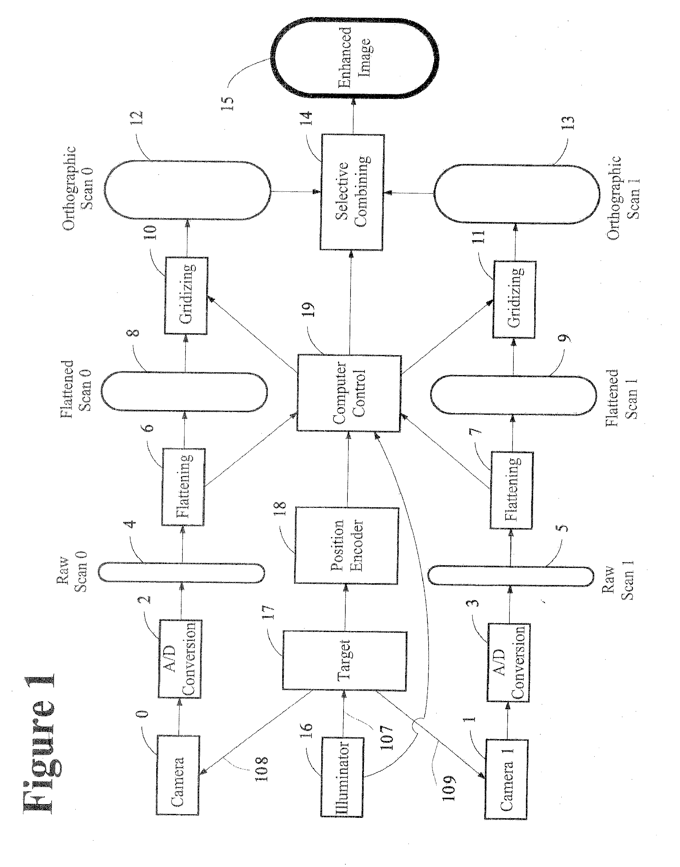
[0106]Referring to FIG. 1, an illuminator 16 shines light 107 on a target object 17. A mixture of diffuse and specular reflection occurs along various beam paths such as at 108 and 109 to Camera 0 and to Camera 1 respectively. Light input to Camera 0 is put through A / D Conversion 2 in an analog / digital converter, which outputs a set of Raw Scan 0 data 4. The Raw Scan 0 data 4 then proceeds through the Flattening 6 process, which corrects each pixel for variance in illumination pattern and camera sensitivity. The Flattened Scan 0 data 8 then proceeds to a Gridizing 10 process, which corrects the data for parallax effect, that is, for the widening of pixel spaces at more oblique angles across the target surface from Camera O′s perspective. The resulting Orthographic Scan 0 data 12 then proceeds to the Selective Combining module 14.

[0107]Likewise, light input to Camera 1 is put through A / D Conversion 3 in an analog / digital converter, which outputs a set of Raw Scan 1 data 5. The Raw Sc...


PUM

PropertyMeasurementUnit
reflectivityaaaaaaaaaa
depth of fieldaaaaaaaaaa

Abstract

This invention provides accurate, high quality images for the identification of the surface characteristics of an object, that may be used as an input to suitable industrial process. It involves acquiring a first raw scan of a portion of a target object across a scan line in a scan zone with a first camera and simultaneously acquiring a second raw scan of the same portion of the target object across the scan line in the scan zone with a second camera. The raw scans are converted to digital and then processed with flattening coefficients derived from measurements of variations in illumination. The first and second cameras sets of flattened image data are then gridized to compensate for parallax, make them orthographic sets of image data that can be compared on a pixel-by-pixel basis with a known or measured geometric profile of the target. A selection of enhanced pixel value for a surface coordinate can then be made, based on both sets of data. The obscuring of surface features by specular reflection can thus be effectively eliminated.

Description

FIELD OF THE INVENTION[0001]This invention relates generally to a method and apparatus for the identification of the surface characteristics of an object, and more particularly to a non-contact system to generate image data representative of surface reflectivity of an object that may be used as an input to suitable industrial process control apparatus.BACKGROUND OF THE INVENTION[0002]The invention will be described primarily in connection with using light to obtain image data representing surface reflectivity of the external surfaces of boards of sawn timber in order to enable the computing of accurate image data of the three-dimensional surface profile of each individual board, for the purpose of adjusting sawing equipment in saw mills. This is important in a world of diminishing resources to optimize the quantity or value of the lumber produced. Image data is assembled from a sequence of surface scans of a board as it moves past a linear sensor of scanning apparatus. A typical sca...

Claims


Application Information

Patent Timeline
Patent Type & Authority Applications(United States)
IPC IPC(8): G06K9/62H04N5/228G01N21/55
CPCG01B11/245G01B11/2545G06T5/007G06T2207/30161G01N21/8986G01N2021/8887
Inventor HERMARY, ALEXANDER THOMASSAHRAEI, MOHAMMAD REZAHERMARY, TERRANCE JOHNBALL, MICHAEL DOUGLAS
Owner HERMARY OPTO ELECTRONICS
Why Eureka
Try Eureka