
Image processing apparatus and image processing system for displaying information about ocular blood flow

a technology of image processing apparatus and image processing system, which is applied in the direction of catheters, instruments, printers, etc., can solve the problems of inability to correctly grasp the blood flow state and the inability to correctly recognize the blood flow sta

Inactive Publication Date: 2012-08-30
CANON KK
View PDF2 Cites 28 Cited by
  • Summary
  • Abstract
  • Description
  • Claims
  • Application Information

AI Technical Summary

Benefits of technology

[0008]According to an aspect of the present embodiment, an image processing apparatus includes an identification unit configured to identify a retinal blood vessel based on a retinal image, a measurement unit configured to measure blood flow information for ...

Problems solved by technology

Therefore, the blood flow state cannot be correctly grasped simply by dividing the SLO image into partial areas and displaying them.
Another issue is that, since the blood vessel diameter varies from position to position, the blood flow state cannot be correctly recognized simply by dividing the SLO image into partial areas and displaying information about the blood flow.

Method used


Image

  • Image processing apparatus and image processing system for displaying information about ocular blood flow
  • Image processing apparatus and image processing system for displaying information about ocular blood flow
  • Image processing apparatus and image processing system for displaying information about ocular blood flow

Examples


Embodiment Construction

[0025]Various exemplary embodiments, and features will be described in detail below with reference to the drawings.

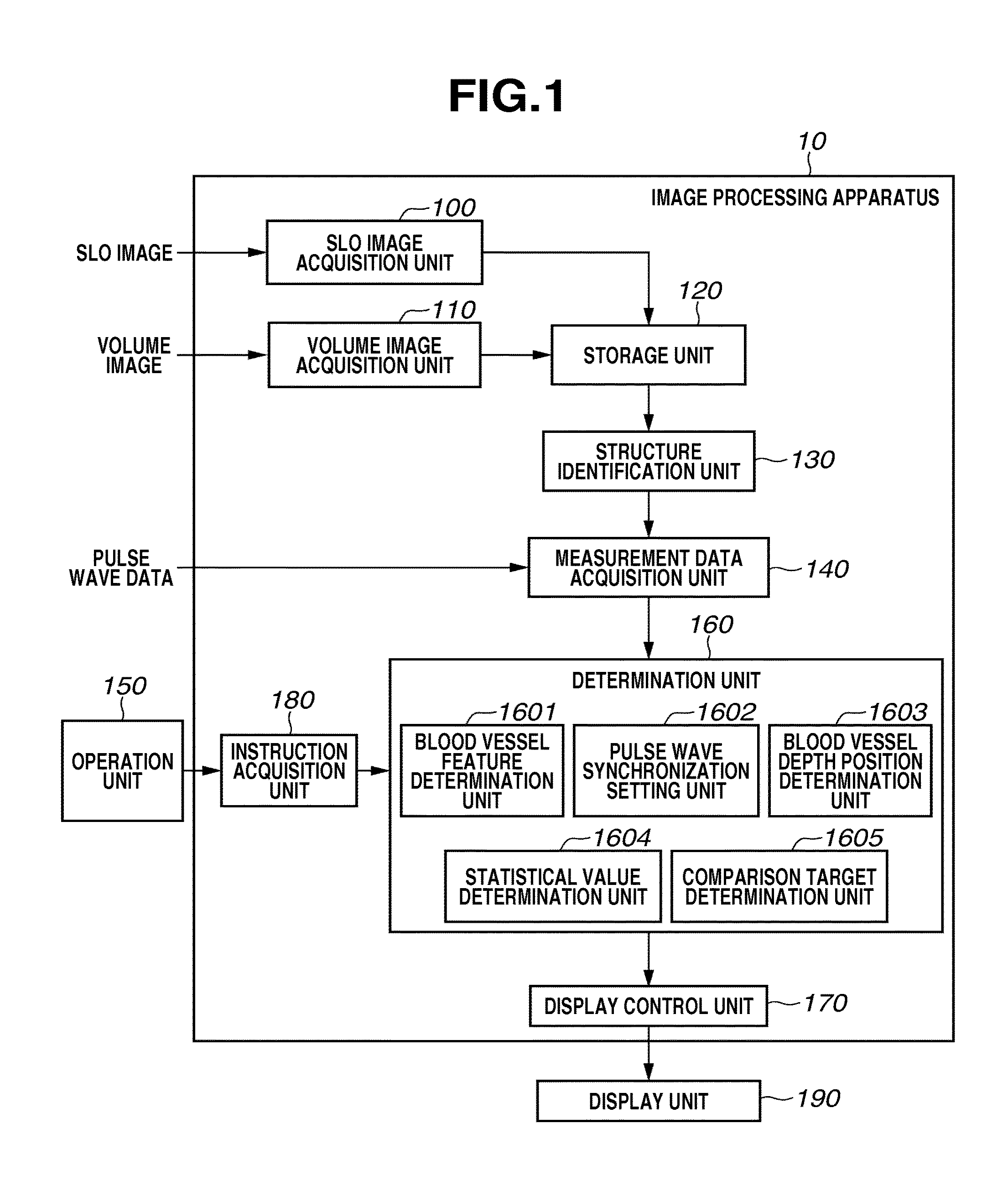
[0026]An image processing apparatus according to a first exemplary embodiment is configured to measure blood flow dynamic states based on an SLO moving image capturing capillaries around a fovea centralis, and to comparatively display statistical values for blood flow dynamic states for each local area in consideration of a blood vessel diameter, the number of pulsation cycles, and a depth position of the capillaries.

[0027]More specifically, the following two cases will be described below: (i) measure the blood flow velocity as a blood flow dynamic state, and comparatively display the measured blood flow velocity between local areas around the macular portion, and (ii) measure the blood flow rate as a blood flow dynamic state, and comparatively display the measured blood flow rate between layers at different depth positions.

[Entire Configuration]

[0028]A functional confi...


PUM


Abstract

An image processing apparatus includes an identification unit configured to identify a retinal blood vessel based on a retinal image, a measurement unit configured to measure blood flow information for the blood vessel based on the retinal image, and a display control unit configured to display the measured blood flow information by at least one selected from a depth of the identified blood vessel, a size of the identified blood vessel, and a combination of both.

Description

TECHNICAL FIELD[0001]The present disclosure relates to an image processing apparatus and an image processing system configured to display information about an ocular blood flow.BACKGROUND[0002]Ocular examinations are widely performed for the purpose of preemptive medical care for lifestyle-related diseases and other diseases occupying major causes of blindness. A scanning laser ophthalmoscope (SLO; hereinafter referred to as an SLO imaging apparatus), an ophthalmology apparatus based on the principle of a confocal laser scanning microscope, performs raster scan on a fundus with a laser beam (i.e., a measuring beam) and, based on the light intensity of a relevant return beam, quickly acquires a high-resolution retinal image.[0003]In recent years, an adaptive optics (AO)-SLO imaging apparatus including an adaptive optics (AO) has been developed. The AO measures an aberration of the subject's eye in real time by a wavefront sensor and corrects the aberration of the measurement beam and...

Claims


Application Information

Patent Timeline
IPC IPC(8): A61B3/14G06K9/00
CPCA61B3/1241A61B3/14A61B3/1025
Inventor IMAMURA, HIROSHI
Owner CANON KK
Learn More