Vibration reduction techniques for jet pump slip joints

a technology of slip joints and vibration reduction techniques, which is applied in the direction of machine/engine, greenhouse gas reduction, nuclear elements, etc., can solve the problems of slip joints being unstable under flow conditions, flow-induced vibration of boiler jet pumps, etc., and achieve the effect of reducing vibration

Inactive Publication Date: 2012-08-30
AREVA NP SAS
View PDF0 Cites 12 Cited by
  • Summary
  • Abstract
  • Description
  • Claims
  • Application Information

AI Technical Summary

Benefits of technology

[0011]Another method for retrofitting a boiling water reactor is also provided. The method includes removing a mixing chamber from a slip joint defined by a diffuser and the mixing chamber, the mixing chamber having an inner surface directing flow to the diffuser and an outer surface defining part of the slip joint and having an insertion depth in the diffuser. The method also includes providing at least one of a new inner surface, a new outer surface and a new insertion depth to permit reduced vibration at the slip joint.

Problems solved by technology

Boiling water reactor jet pumps experience flow induced vibrations.
Although this helps facilitate putting the top piece in the bottom piece, these leave the slip joint unstable under flow conditions with sufficiently high differential pressure.

Method used


Image

  • Vibration reduction techniques for jet pump slip joints
  • Vibration reduction techniques for jet pump slip joints
  • Vibration reduction techniques for jet pump slip joints

Examples


Embodiment Construction

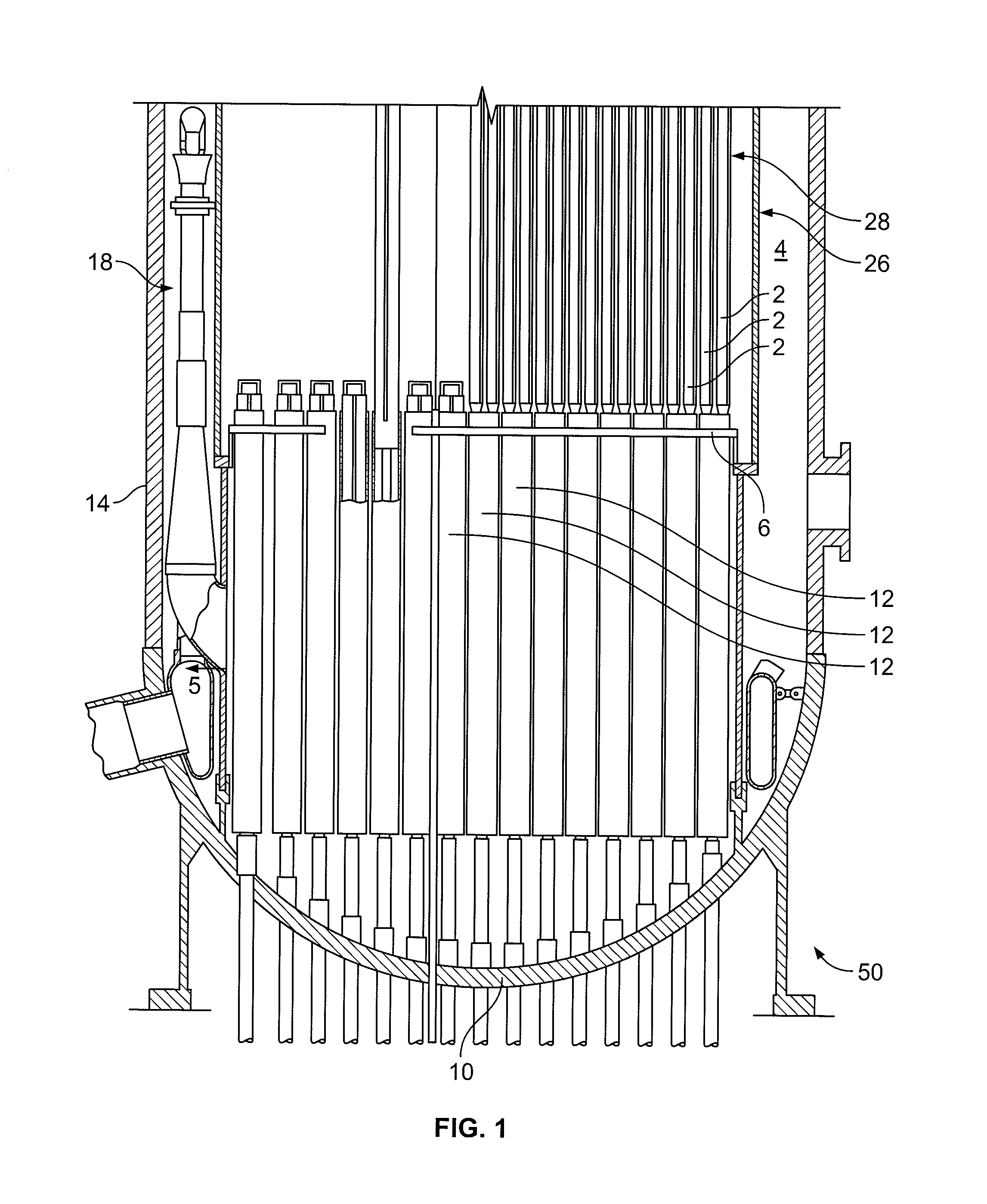
[0028]FIG. 1 schematically shows the lower portion of a boiling water nuclear reactor 50. Reactor 50 includes a pressure vessel 14 closed at a lower end by a dish shaped bottom head 10. A shroud 26 is located radially inside of pressure vessel 14. Between a wall of pressure vessel 14 and shroud 26 is a downcomer annulus 4. A reactor core fuel assembly 28 is housed inside of shroud 26, which comprises fuel assemblies 2. Fuel assemblies 2 may be arranged in groups of four, with each group being attached to guide tubes 12 at lower ends of fuel assemblies 2. Upper ends of guide tubes 12 are sealed by a horizontal bottom grid plate 6 mounted across the bottom of shroud 26. Multiple jet pumps 18, one of which is shown schematically in FIG. 1, are mounted in downcomer annulus 4 circumferentially spaced about shroud 26.

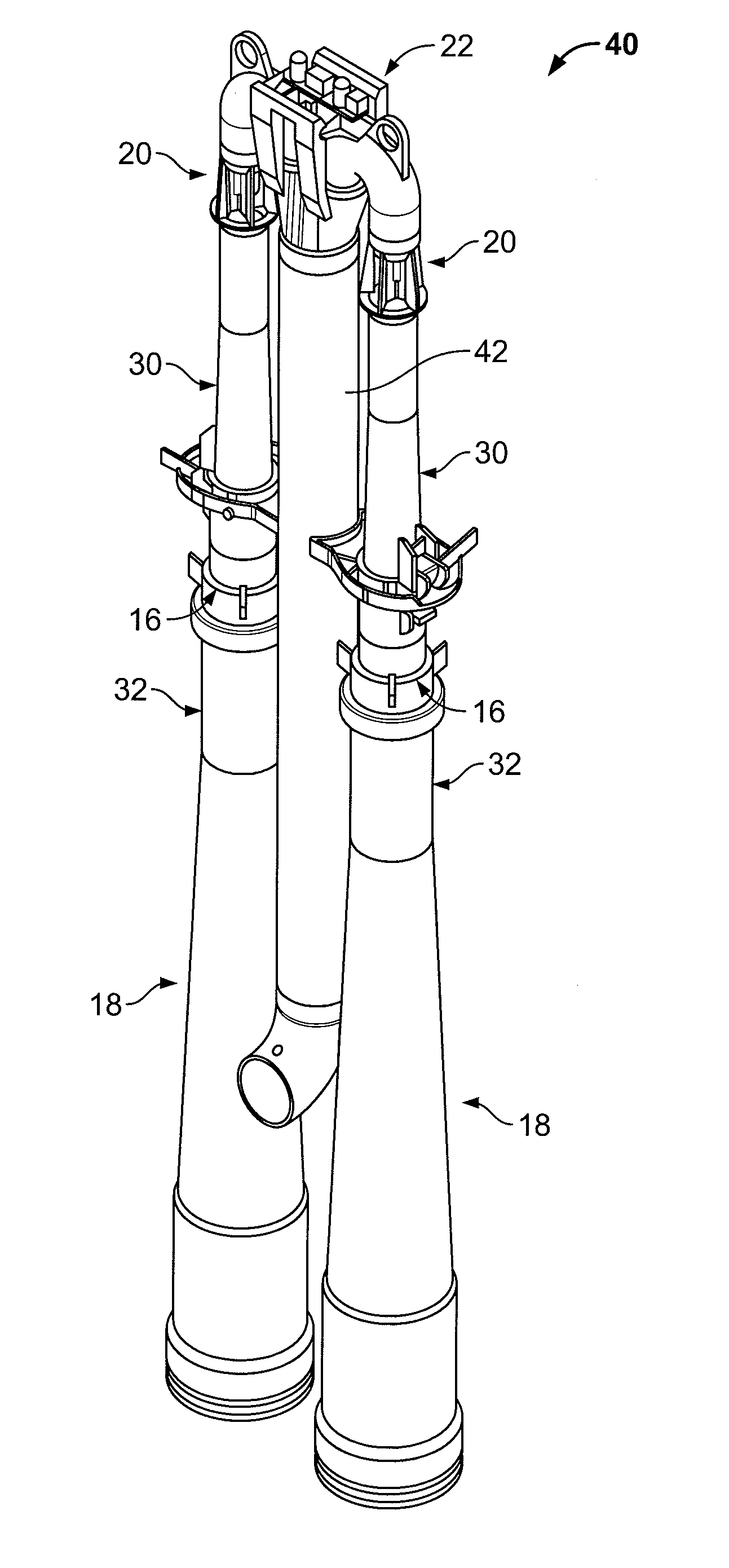
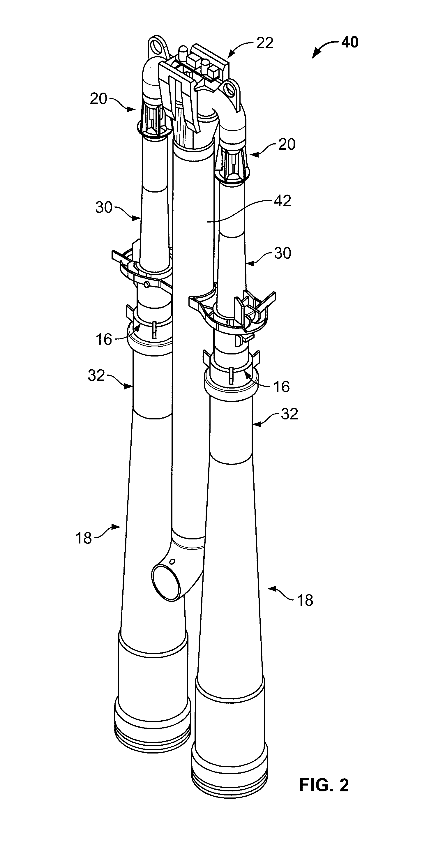
[0029]FIG. 2 shows an isometric view of a jet pump assembly 40. Jet pump assembly 40 includes two jet pumps 18 that are coupled to a riser pipe 42 by a ram's head 22. Water e...


PUM

PropertyMeasurementUnit
height h1aaaaaaaaaa
height h1aaaaaaaaaa
thicknessaaaaaaaaaa

Abstract

A method for retrofitting a boiling water reactor is provided. The method includes removing a mixing chamber from a slip joint defined by a diffuser and the mixing chamber, the mixing chamber having an inner surface and a bottom edge directing flow to the diffuser such that a recirculation zone at an entrance to the slip joint creates a diverging effective path for the leakage flow entering the slip joint. The method also includes providing a new inner surface and new bottom edge, the new inner surface and the new bottom edge being reshaped to decrease the size of the recirculation zone. A jet pump is also provided.

Description

[0001]Priority to U.S. Provisional Patent Application Ser. No. 61 / 446,630 filed Feb. 25, 2011, is claimed, the entire disclosure of which is hereby incorporated by reference.[0002]The present invention relates generally to a jet pump of a boiling water nuclear reactor and more specifically to a jet pump slip joint for vibration reduction.BACKGROUND[0003]Jet pumps are used to circulate a coolant fluid, such as water, through the fuel core of a boiling water nuclear reactor. The jet pumps are located in a downcomer annulus between a shroud surrounding the core and the interior of the pressure vessel where the coolant is forced into the inlet end or bottom of the core. A slip joint is used along the length of the jet pump typically to accommodate differential thermal expansion that may occur along the jet pump. The slip joint typically has a narrow gap between two nearly concentric cylinders through which coolant fluid may pass under differential pressure.[0004]Boiling water reactor je...

Claims


Application Information

Patent Timeline
Patent Type & Authority Applications(United States)
IPC IPC(8): G21C15/25B23P6/00
CPCF04F5/464Y10T29/49721Y02E30/31G21C15/25Y02E30/30
Inventor LYNCH, JOHN JOSEPH
Owner AREVA NP SAS
Why Eureka
Try Eureka