Assembly device provided with a visual reference mark and method for the assembly thereof

Inactive Publication Date: 2012-09-06
LISI AEROSPACE
View PDF13 Cites 2 Cited by
  • Summary
  • Abstract
  • Description
  • Claims
  • Application Information

AI Technical Summary

Benefits of technology

[0022]The invention therefore has many advantages. It specifically allows the operator to save time because he no longer has to perform two operations consisting of measuring the actual thickness of the elements to be attached and tightening the nut to verify his device thickness selection. No means for a gauge or calibration type control measurement is now necessarily. Also, because assembly devices that have already been installed are not reused in aircraft assemblies, rejected ones are thrown away in the prior art, representing a significant waste that the invention now proposes to prevent. Finally, the device selection according to the invention is certain and reliable.

Problems solved by technology

In practice, however, because it is difficult and tedious to measure this thickness, the result is approximate or even incorrect.
Additionally, the assembly of the assembly device itself can causecompression of the elements to be assembled at the location where the assembly device is mounted due to a lack of hardness of an interposed mastic applied between said elements;an elongation of said device in response to the exerted force, from one side, by a head of said device and, from the other side, by either a nut or a swage collar.
All of these inaccuracies can easily result in an incorrect selection regarding the length of assembly device and cause a device to be assembled with a wrong length.
If the operator realizes his incorrect selection, there is a significant loss of material and time because he must, in a second operation, dismantle the device that can no longer perform its function in most cases and reassemble, in a third operation, as many times as necessary, another specific assembly device, called “oversize”.
If he does not realize his incorrect selection, this mistake has serious consequences for the strength of the structure being assembled.
The method for determining the device length in the prior art is therefore long, tedious, inaccurate, costly, and dangerous.

Method used


Image

  • Assembly device provided with a visual reference mark and method for the assembly thereof
  • Assembly device provided with a visual reference mark and method for the assembly thereof
  • Assembly device provided with a visual reference mark and method for the assembly thereof

Examples


first embodiment

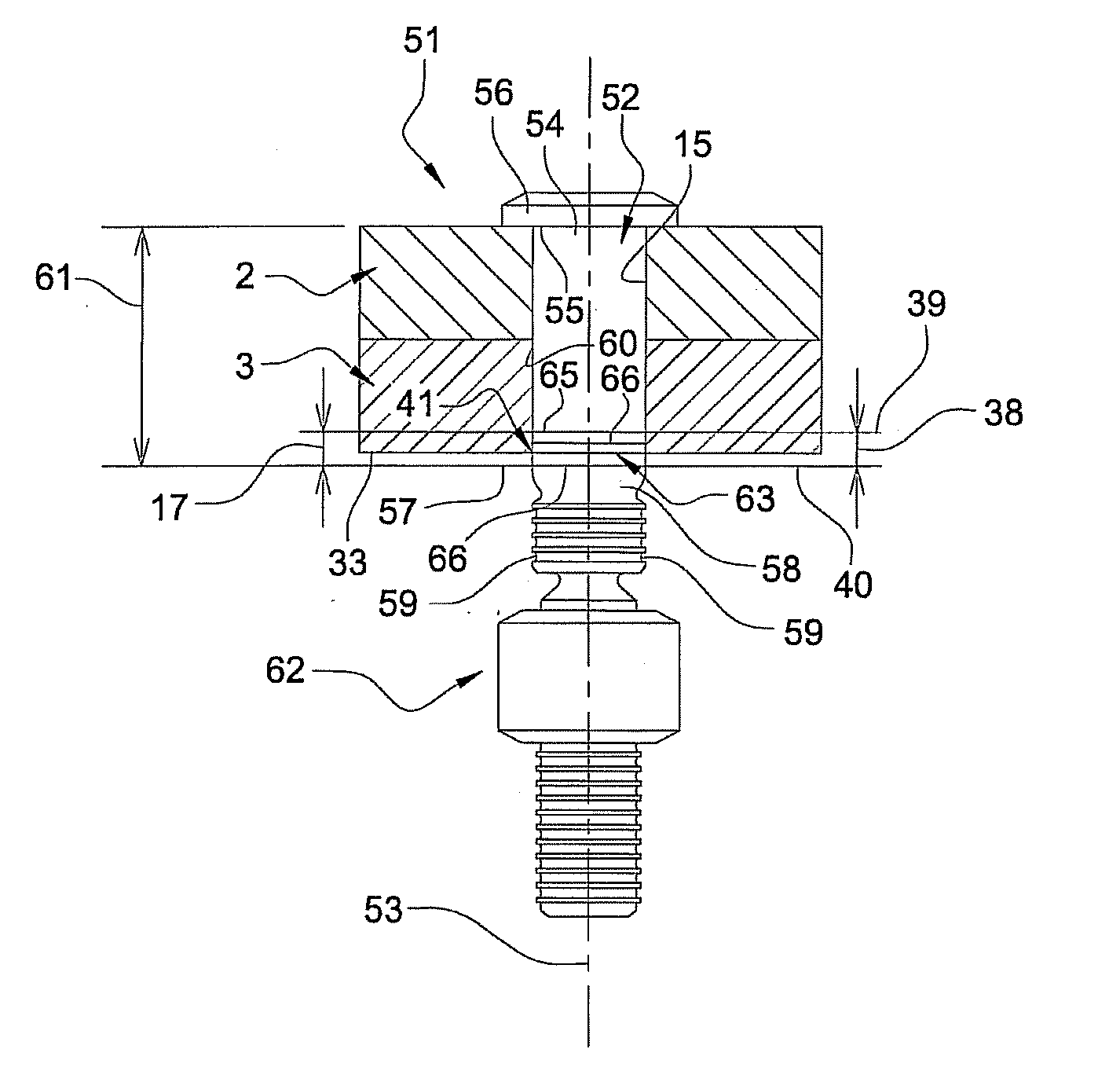
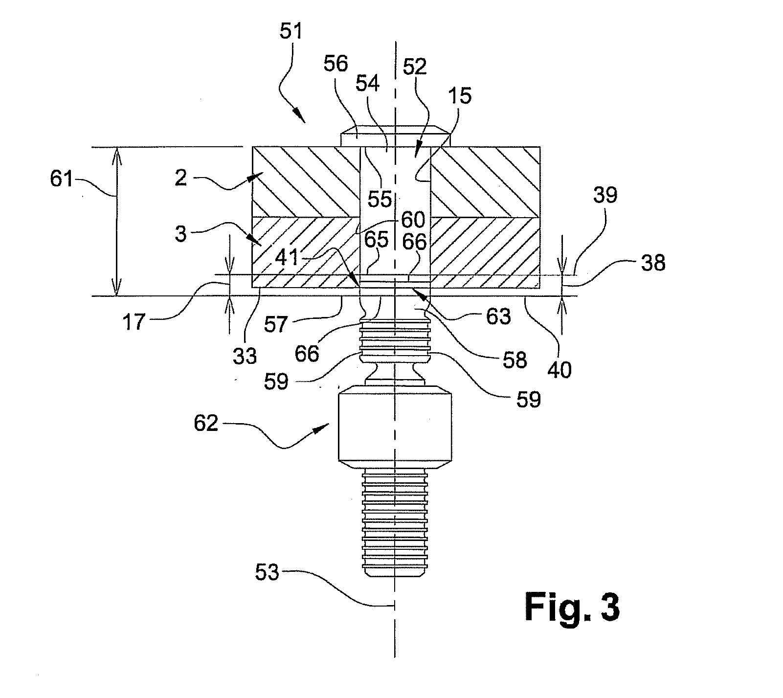
[0072]In the invention, the visual reference mark has only one circular marking at its upper limit 65.

second embodiment

[0073]In the invention, the visual reference mark has a first circular marking on the shank and a second marking on the second end of the shank.

[0074]The device 51 is a good length selection, appropriate for the actual thickness of the elements 2 and 3 to be assembled because the visual reference mark 63 is visible by the operator without fully protruding from the lower element 3.

[0075]More specifically, an edge 41, formed by the circular intersection between the bore 15 and the bottom surface 33, is in contact with the reference mark.

[0076]Alternatively, the device 61 may further comprise a sleeve on which a visual reference mark is provided. Preferably, this visual reference mark is configured in the same manner as the sleeve 30 shown in FIGS. 1 and 2.

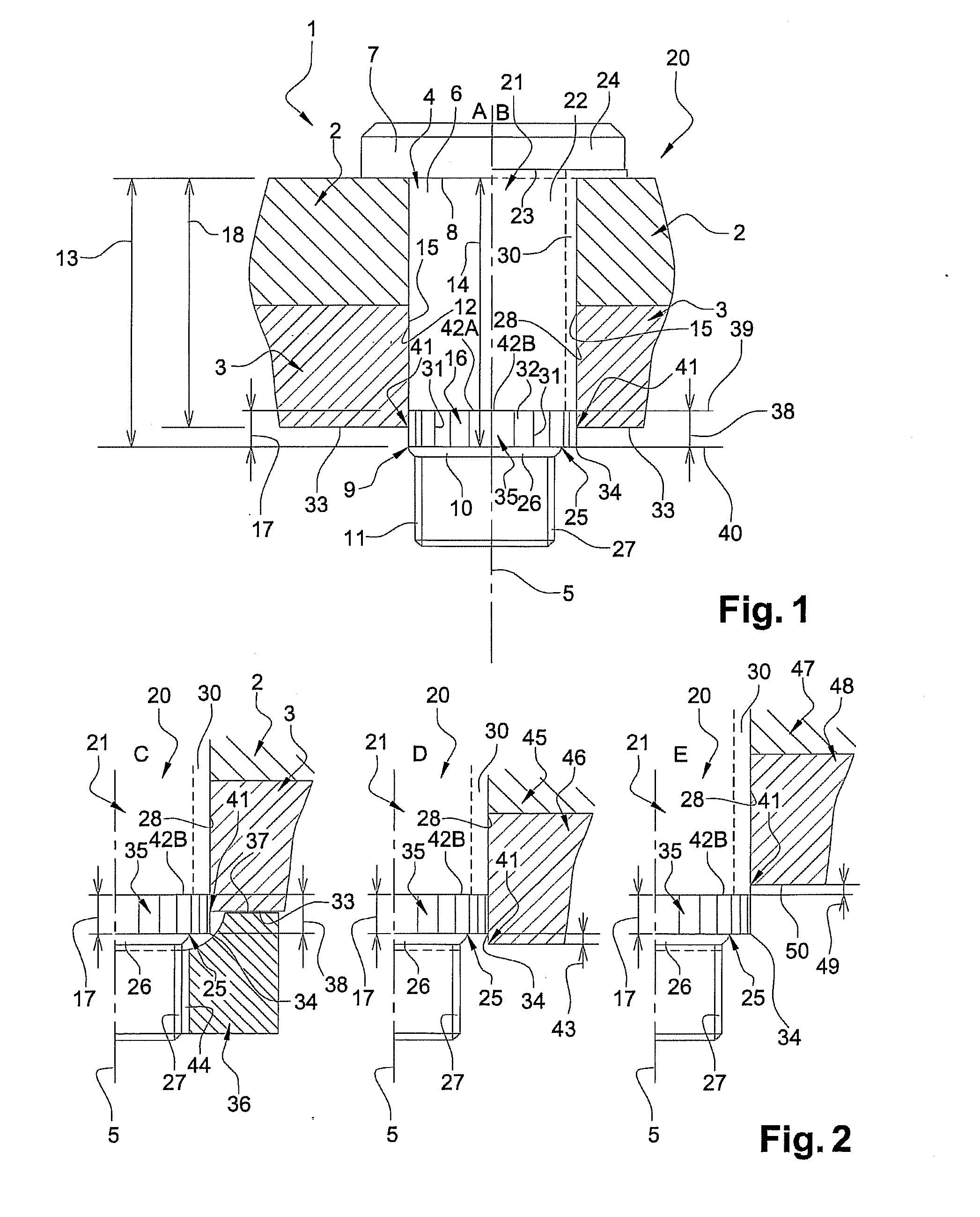
[0077]A method for assembling the elements (2, 3) using the device 51, alone or with a sleeve, comprises a step for selecting the size of said device 51. This step is similar to the step described above for devices 1 and 20 (FIG. 2) ...


PUM

PropertyMeasurementUnit
Fractionaaaaaaaaaa
Currentaaaaaaaaaa
Digital informationaaaaaaaaaa

Abstract

The invention relates to a device (1; 20; 51) for assembling pre-bored (15) elements (2; 3), the elements together having a reference thickness (18) that may vary up to an actual maximum thickness (40), the device comprisinga male element (4; 21; 52) comprising a shank (6; 22; 54) extending in a thread (11; 27) or swaging grooves (59),an external surface (12; 28; 60) having a height (13; 61) equal to a height (14) of the shank, chosen so as to correspond to at least the actual maximum thickness (40) of the elements to be assembled,characterized in that the external surface has a visual reference mark (16; 35; 63), located at a distance (17) of a lower limit (9; 34; 57), or extending over a distance (17) from a lower limit up to an upper limit (42A; 42B; 65) toward the head.

Description

TECHNICAL FIELD OF THE INVENTION[0001]This invention relates to an assembly device provided with a visual reference mark. The technical field of the invention is, generally, that of fasteners. More specifically, the invention relates to screws, nuts, swaging grooves fasteners, swage collars, and sleeves intended to fasten structural elements of a device, such as pre-bored aircraft elements.TECHNOLOGICAL BACKGROUND OF THE INVENTION[0002]In the prior art, when mounting assembly devices on a structure, the operator must, in a first operation, measure the actual thickness of the structure to be assembled to select a fastening device with an appropriate length because a difference may exist between a theoretical reference thickness, known by the operator, and an actual thickness, this difference being due to varying manufacturing tolerances that exist in the area of the assembly, specifically in the thickness of the structural elements.[0003]In practice, however, because it is difficult ...

Claims


Application Information

Patent Timeline
IPC IPC(8): B23P11/00
CPCF16B1/0071F16B5/025Y10T29/49778Y10T29/4978Y10T29/49764F16B2200/95
Inventor VERDIER, FLORENT
Owner LISI AEROSPACE
Why Eureka
Try Eureka