Motorized window shade system

a motorized and window shade technology, applied in the field of window shades, can solve the problems of insufficient existing motorized window shade systems, inflexible methods, and inability to adjust the glass angle, so as to prevent the contact of the shade with the glass, avoid accidental breakage, and minimize light reflections

Inactive Publication Date: 2012-09-06
VORYAN +3
View PDF6 Cites 3 Cited by
  • Summary
  • Abstract
  • Description
  • Claims
  • Application Information

AI Technical Summary

Benefits of technology

[0014]The cable is designed to withstand continual sun exposure and is constantly retractable via a spring contained within the box. The spring is tempered steel flat and wound to create an even overall pull. The loop prevents the cable from retracting inside the box. The cable attaches to the shade's bottom hembar via connection between its loop and stainless steel hook bolted to the hembar. Its durable construction avoids accidental breakage by controllers, maintenance personnel, or similar.
[0015]When mounted at a proper distance from the cab glass, the present invention spring box keeps the shade material on a plane similar to the glass. This helps minimize light reflections and prevents shade contact with the glass. It does so securely, reliably, and without the drawbacks of previously used methods. The shade material is pulled taught and does not contact the glass. Neither the Spring Box nor any of its components contact the glass, removing the possibility of scratching or damage to the glass. The Spring Box's cable can be easily detached and reattached to the bottom hembar so the shade can be uninstalled, serviced, or cleaned.

Problems solved by technology

Existing motorized window shade systems are relatively slow, inflexible, and use flawed methods of glass angle slope simulation.
In the leading requirements, safety and performance were of great importance and existing motorized shade systems were not adequate.

Method used


Image

  • Motorized window shade system
  • Motorized window shade system
  • Motorized window shade system

Examples


Embodiment Construction

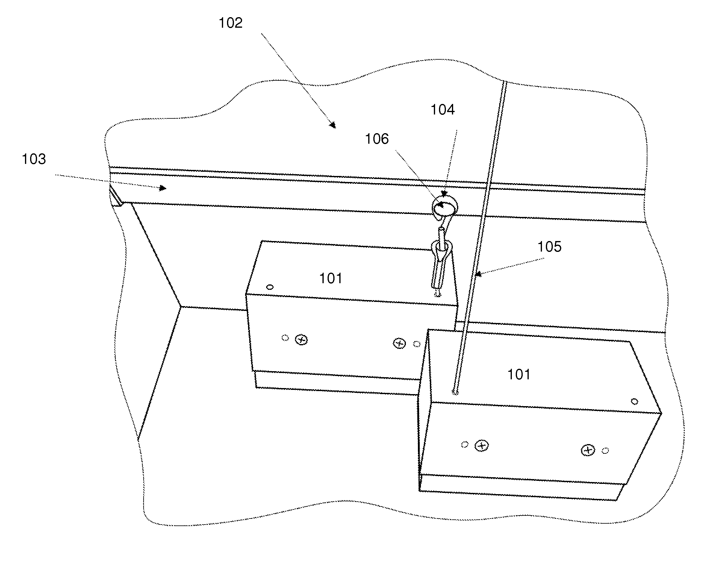
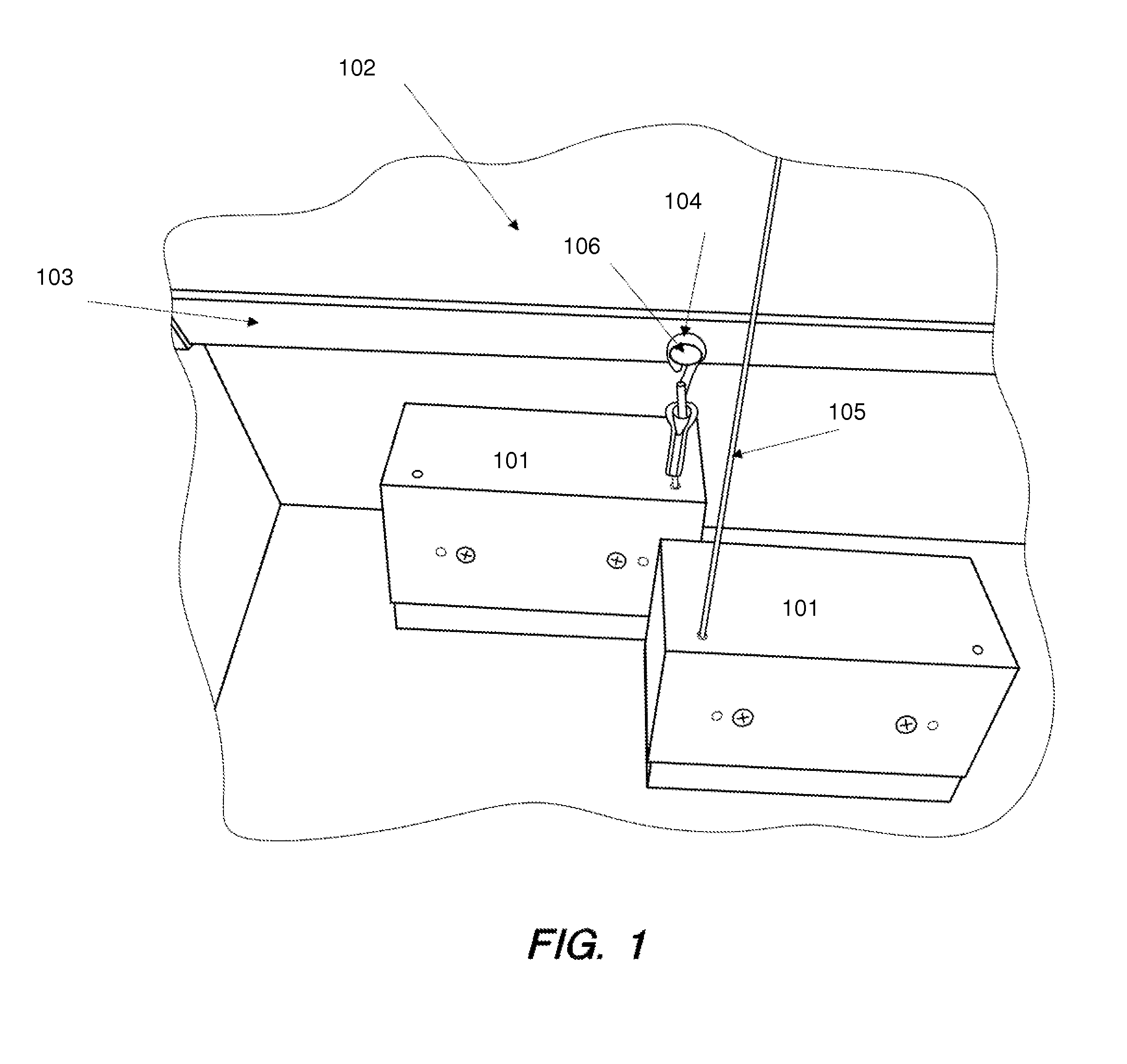
[0018]As shown in FIG. 1 and FIG. 2, the present invention's spring boxes 101 are ideally mounted beneath the level of the windowsill. In addition to being aesthetically preferable, this prevents a horizontal light gap that results from the shade 102 not being fully drawn down to the windowsill due to the spring box 101 height. Otherwise, the shade's bottom hembar 103 draws to a point where it contacts the spring box 101 and can pull down no further.

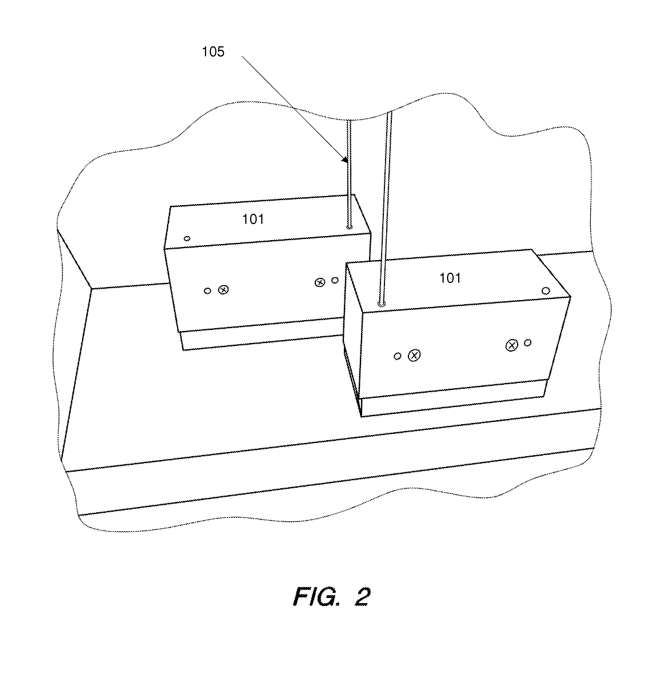
[0019]Alternatively, the spring boxes 101 can be mounted on their sides in situations where they cannot be recessed beneath the windowsill. The mounting location is ideally centered on the loop 104 attached to the hembar 103 at the hembar stanchion 106. However, this is not an absolute requirement. The spring box cable 105 can then route through one or more free moving, non clutch pulleys (not shown) before attaching to the hembar 103. The final pulley must be centered on the hembar loop 104, and this ensures the shade draws and retracts...


PUM


Abstract

An improved Air Traffic Control Tower cab window shade system is presented, utilizing a faster motor than in prior art ATCT applications. The present invention's motor operates at 80 rpm and raises the shade material at 9.62 inches per second on a 2.3-inch diameter roller tube. This allows an average 8 foot high shade to fully raise in 10 seconds. The shade is half raised in about 5 seconds.
The improved speed is due to a spring box at the bottom end of the shade, providing constant tension to the shade and permitting the shade to be retracted safely at higher speed without risking scratching the cab window glass.

Description

RELATED APPLICATIONS[0001]This application claims the benefit of U.S. Provisional Application 61 / 448,627, filed Mar. 2, 2011, whose contents are included here by reference.FIELD OF THE INVENTION[0002]This invention relates to the field of window shades for structures with sloped windows, such as air traffic control towers, and window shade systems.BACKGROUND OF THE INVENTION[0003]Existing motorized window shade systems are relatively slow, inflexible, and use flawed methods of glass angle slope simulation. For example, the Federal Aviation Administration (FAA) had a requirement for a motorized shade system at the main Los Angeles International Airport (LAX) Air Traffic Control Tower (ATCT) cab in 2010. In the leading requirements, safety and performance were of great importance and existing motorized shade systems were not adequate. The present motorized window shade system serves the needs of air traffic controllers more effectively, not only at LAX, but at other ATCTs in the futur...

Claims


Application Information

Patent Timeline
Patent Type & Authority Applications(United States)
IPC IPC(8): E06B9/56
CPCE06B9/42E06B2009/425E06B9/68
Inventor VOGES, RYANVOGES, SONNY C.SMITH, RALPH L.VREELAND, JAY A.
Owner VORYAN
Why Eureka
Try Eureka