Heat sink assembly

Active Publication Date: 2012-09-06
HUANG TSUNG HSIEN
View PDF22 Cites 6 Cited by
  • Summary
  • Abstract
  • Description
  • Claims
  • Application Information

AI Technical Summary

Benefits of technology

[0005]The instant disclosure has been accomplished under the circumstances in view. It is one object of the instant disclosure to provide a heat sink assembly, which has the characteristics of light weight, low manufacturing cost, ease of manufacturing and high heat transfer rate.
[0007]For the heat sink assembly of the instant disclosure, heat is transferred directly from the heat source to the heat pipe in raising the heat transfer performance. Also, the omission of the heat-transfer plate decreases the weight of the heat sink assembly. Furthermore, the adoption of the solder-less press-fit technique reduces the manufacturing cost and simplifies the manufacturing process.

Problems solved by technology

Also, the omission of the heat-transfer plate decreases the weight of the heat sink assembly.

Method used


Image

  • Heat sink assembly
  • Heat sink assembly
  • Heat sink assembly

Examples


Embodiment Construction

[0017]The various objects and advantages of the instant disclosure will be more readily understood from the following detailed descriptions when read in conjunction with the appended drawings. However, the appended drawings are for references and explanation purposes only, therefore are not used to restrict the scope of the instant disclosure.

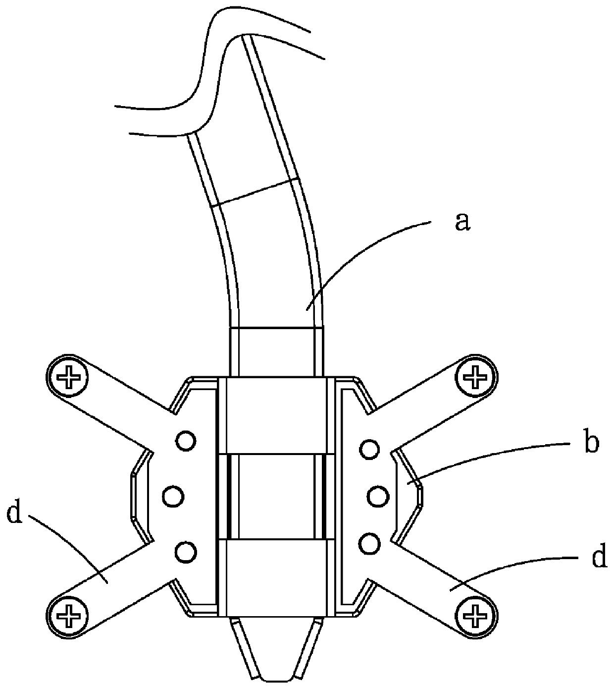
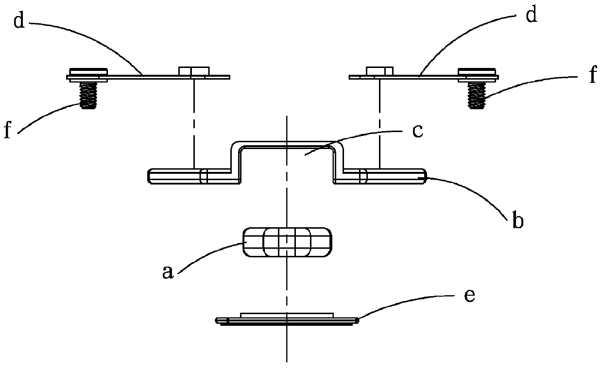
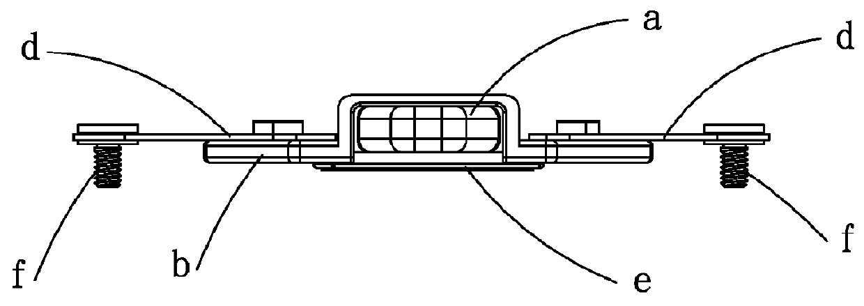
[0018]Please refer to FIGS. 4-9, which show a heat sink assembly comprising a heat pipe 1, two metal support members 2, and a mounting spring plate 3.

[0019]The heat pipe 1 has a first heat-receiving surface 11.

[0020]Each metal support member 2 has a second heat-receiving surface 21.

[0021]The mounting spring plate 3 has; a heat pipe mounting portion 31, which can be, preferably, an inverted conical recess formed thereon for engagement with the heat pipe 1 by means of solder-less press-fit; two support portions 32 joined with respective metal support members 2; and four mounting portions 33 for fixation to a heat source carrier frame 91 that carr...


PUM


Abstract

A heat sink assembly includes a heat pipe, a plurality of metal support members, and a mounting spring plate. The heat pipe has a first heat-receiving surface. Each metal support member has a second heat-receiving surface. The mounting spring plate has a heat pipe mounting portion for securing the heat pipe by a solder-less press-fit means, a plurality of support portions affixed to respective metal support members, and a plurality of mounting portions for securing to a base of a heat source. After the heat pipe is secured to the mounting spring plate, the first heat-receiving surface of the heat pipe would be protruded from the mounting spring plate. The second heat-receiving surfaces of the metal support members are flushed with the first heat-receiving surface of the heat pipe. Thereby, heat is transferred directly from the heat source to the heat pipe to improve heat transfer efficiency, and the weight of the heat sink can be reduced. In addition, by adopting the solder-less press-fit means, the manufacturing cost and process can be lowered and simplified respectively.

Description

BACKGROUND OF THE INVENTION[0001](a) Field of the Invention[0002]The instant disclosure relates to heat sink technology; more particularly, to a heat sink assembly having a heat pipe in direct contact with the heat source for enhancing heat transfer efficiency.[0003](b) Description of the Prior Art[0004]Referring to FIGS. 1-3, a conventional heat sink comprises a heat pipe a, a locating member b, two fixation spring plates d, and a heat-transfer plate e. The locating member b has a recess c formed thereon. The heat pipe a is soldered to the recess c of the locating member b with a solder paste. The two fixation spring plates d are fastened to two opposite sides of the locating member b. The heat-transfer plate e is soldered underneath the heat pipe a and the locating member b with a solder paste. Screws f are inserted through the spring plates d and screwed into a heat source carrier frame to affix the heat sink thereon. The heat-transfer plate e is kept in contact with the heat sou...

Claims


Application Information

Patent Timeline
IPC IPC(8): F28F9/007
CPCF28F9/002F28D15/02F28D15/0275H01L23/36H05K7/20
Inventor HUANG, TSUNG-HSIEN
Owner HUANG TSUNG HSIEN
Why Eureka
Try Eureka