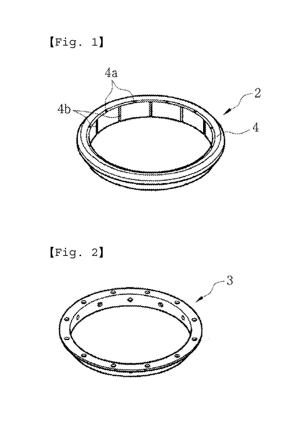
However, these holes and vertical grooves are prone to be abraded away when the seal is mounted axially on the track and then is used for a long period time.
There may occur a problem in that the abraded holes 4a and vertical grooves 4b cause oil to be leaked to the outside or foreign substances such as
moisture or
dust particles to easily infiltrate into the seal.
Thus, the conventionally embodied seal 2 entails a problem in that since it employs the annular reinforcing
metal core 3 serving as a support when in use for a long period of time, so that once crushed or deformed by a large force or pressure, it does not return immediately to its original shape, which makes it impossible to function as an O-ring.
In addition, when the seal rusts to be corroded, its shape itself is expanded, which makes it impossible to perform a tight sealing function to cause leakage of oil.
Further, when foreign substances such as
moisture or
dust particles infiltrate into the seal, a shaft of the track rotatably driving the track is corroded and deterioration of oil due to infiltration of
moisture is accelerated, leading to a damage of expensive heavy equipments or tracked vehicles or a reduction in the endurance lifespan.
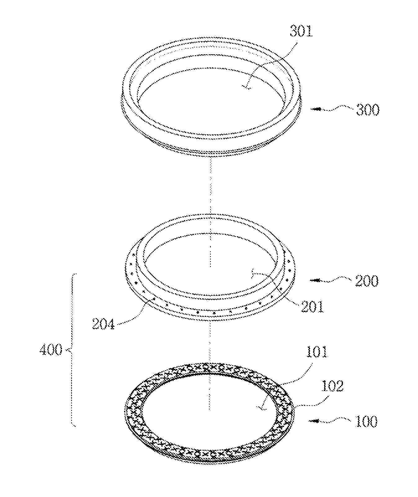
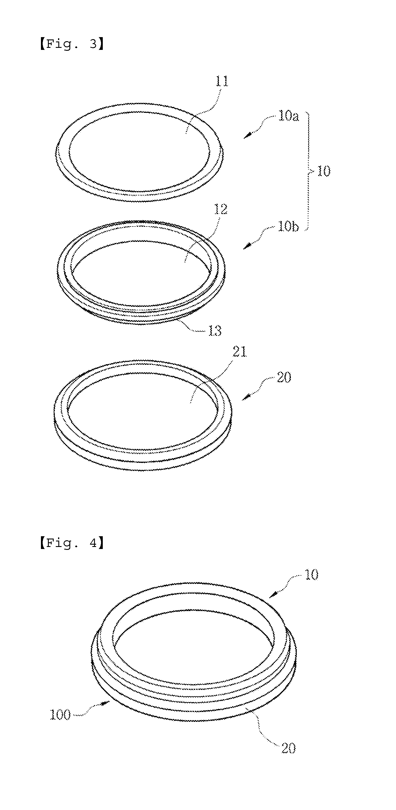
However, the link seal 100 encounters problems in that the link seal 100 and a
bushing abutting against the outer circumference of the link seal 100 are brought into
close contact with each other while a certain force is exerted therebetween by the rotation of the
bushing to create a
high load exceeding a given value and a frictional heat.
In addition, if an external
high load and a frictional heat are transmitted to the link seal 100 for a certain period of time, the sealing part 10b acting as a sub-body constituting a link seal
assembly is abraded away, and resultantly the sub-body 10b may be separated from the main body 10a or broken, which leads to having an influence on the driving power and the endurance lifespan of the expensive equipment.
Such a link seal, however, still involves a problem in that the link seal mounted on the track shaft of a tracked vehicle can be separated from the track shaft or is damaged under the worst conditions like the above-mentioned problems.
Moreover, there has been a problem in that a slip or spin phenomenon occurs between the seal body and the
cushion member formed of the
rubber ring, which constitute the link seal
assembly.
Thus, the rubber ring serving as the
cushion member is separated from the seal body to cause the rubber ring to be rotated, which leads to a spin or slip phenomenon.
Such a slip phenomenon enables heat to be generated from a contact surface between the two different members by friction, so that deterioration of the seal body and excessive abrasion of the rubber ring serving as the cushion member occur, and ultimately an
intrinsic function of the link seal is lost and even a lifespan of the expensive equipment is affected by the slip phenomenon.
Such a conventional link seal, however, still encounters a problem in that the link seal is separated from the track shaft of a tracked vehicle under the worst conditions even in the case where a link seal includes various shapes of profiles 85a and 85′ formed on the outer surface of a sleeve as shown in FIGS. 8 and 9 instead of the splines 84.

