Optical device, display device, and lighting device

a technology of optical devices and display devices, applied in the field of optical devices, can solve the problems of lowering the luminance of light extracted outside, and achieve the effects of improving the luminance of light extracted outsid

Inactive Publication Date: 2012-09-06
SEMICON ENERGY LAB CO LTD
View PDF17 Cites 22 Cited by
  • Summary
  • Abstract
  • Description
  • Claims
  • Application Information

AI Technical Summary

Benefits of technology

[0057]The color conversion unit is provided with a color filter region and a transmissive region, whereby luminance of light extracted outside can be improved.
[0058]That is, luminance of light passing through the color filter is compensated by that of light passing through the transmissive region, whereby luminance of light extracted outside is improved.
[0059]By the provision of a color filter, a lighting device with which a desired color is expressed using a material with high luminance or a material with high reliability that does not easily deteriorate can be provided.

Problems solved by technology

The color of light can. be easily converted using a color filter; however, there is a problem in that luminance of light extracted outside is lowered when the light passes through the color filter.

Method used


Image

  • Optical device, display device, and lighting device
  • Optical device, display device, and lighting device
  • Optical device, display device, and lighting device

Examples


embodiment 1

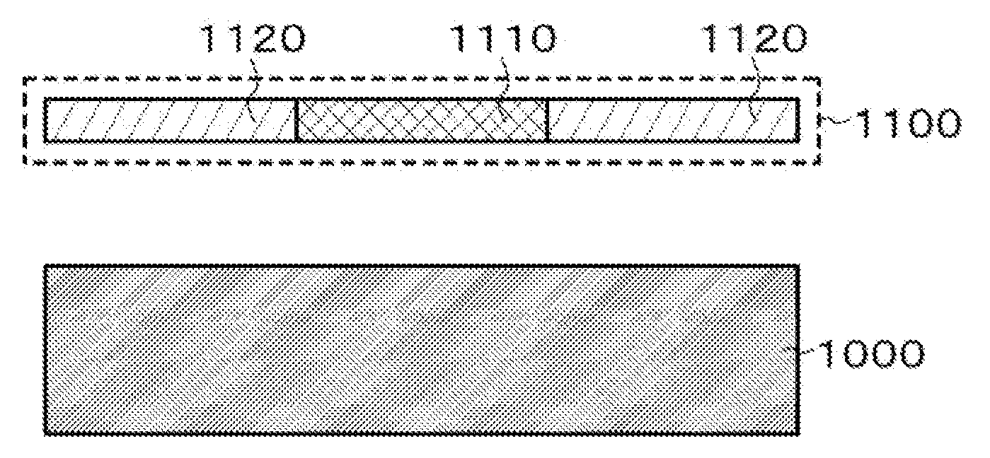
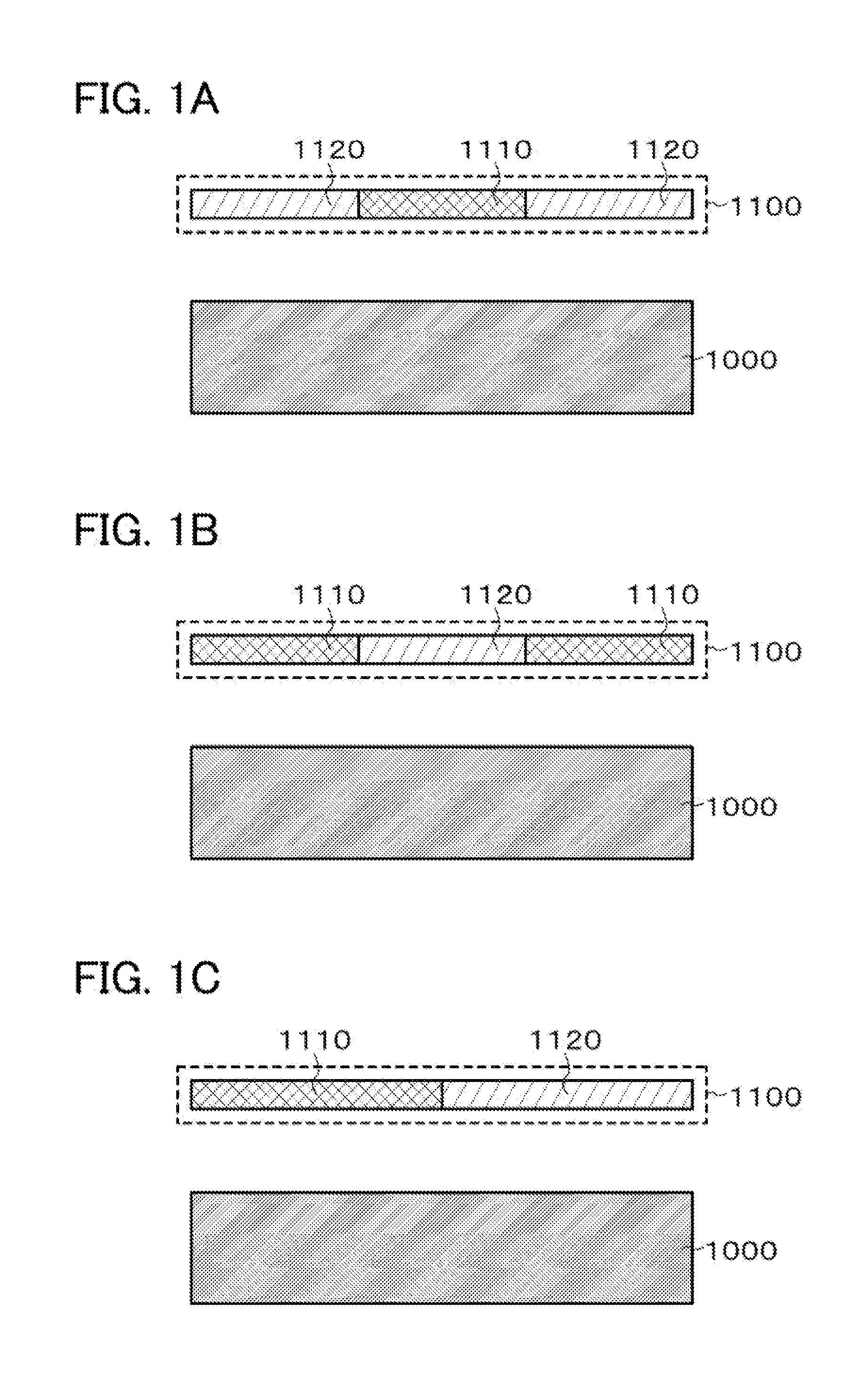
[0096]In FIGS. 1A to 1C, optical devices each include an optical element 1000 and a color conversion unit 1100 which light radiated from the optical element 1000 (light emitted from the optical element or light passing through the optical element 1000) enters.

[0097]Further, in each of the optical devices in FIGS. 1A to 1C, the color conversion unit 1100 has a color filter region 1110 in which a color filter layer is provided, and a transmissive region 1120 having higher transmittance per unit area than the color filter region 1110.

[0098]The following can be given as examples of the structures of the transmissive region 1120; a structure on which the color filter layer is removed, a structure in which the color filter layer is locally thinned, a structure in which a light-transmitting color filter layer containing a dye material (e.g., a pigment) the amount of which is smaller than that of a dye material contained in the color filter layer in the color filter region 1110 is provided....

embodiment 2

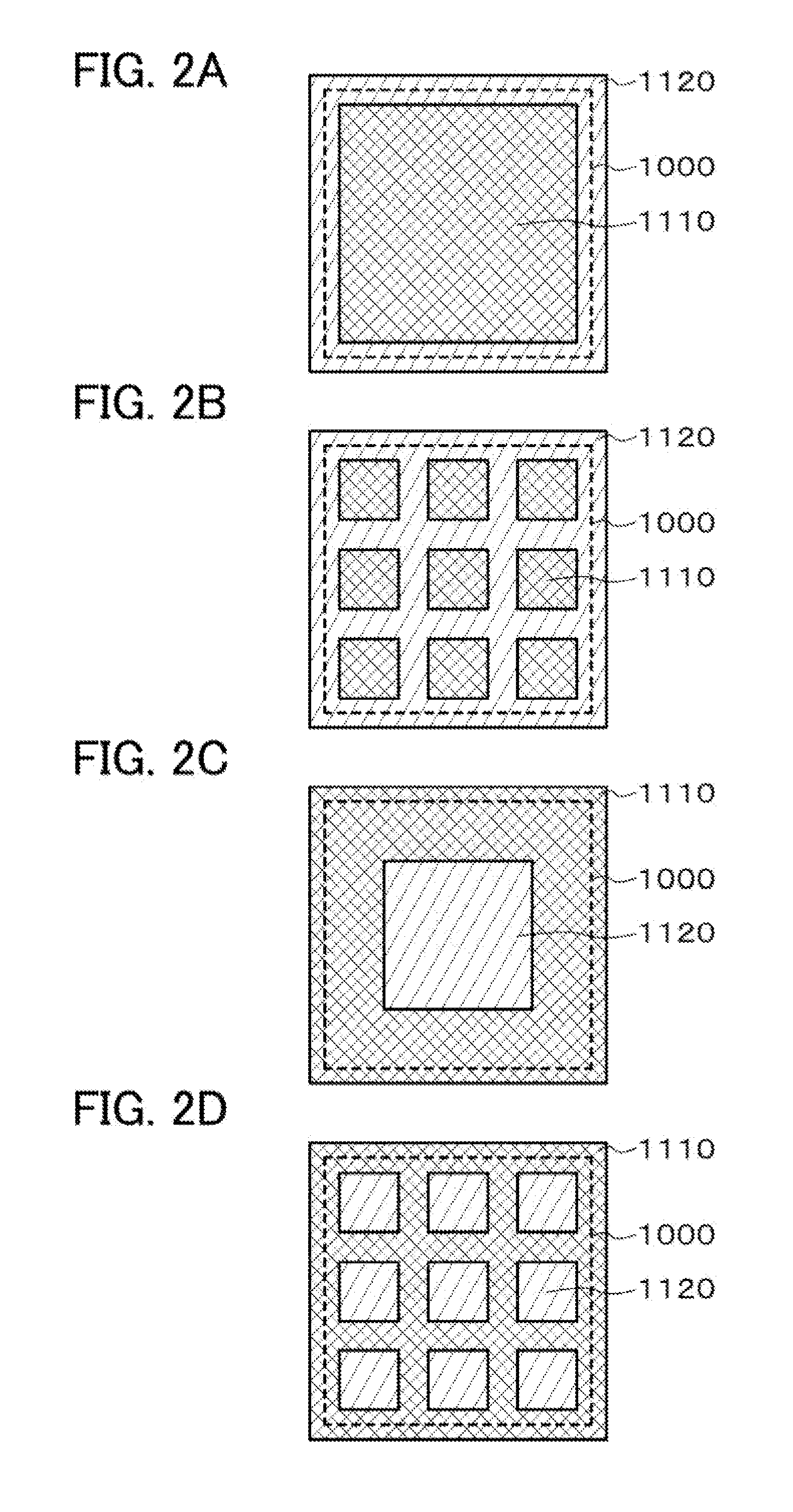
[0114]FIGS. 2A to 2D each illustrate an example of a plan view showing a positional relation between the optical element 1000 and the color conversion unit (the color filter region 1110 and the transmissive region 1120).

[0115]Note that the portions shown by dashed litres are end portions of the optical elements 1000 in FIGS. 2A to 2D.

[0116]Further, FIGS. 2A to 2D each illustrate one unit (e.g., one pixel in the case of a display device).

[0117]The optical element 1000, the color filer region 1110, and the transmissive region 1130 each have a square shape to FIGS. 2A to 2D; however, the shapes are not limited thereto, and the optical element 1000, the color filter region 1110, and the transmissive region 1120 may have any shapes.

[0118]In FIGS. 2A and 2B, the area of the color filter region 1110 is smaller than that of the optical element 1000.

[0119]Specifically, the color filter region 1110 has an island, shape that is slightly smaller than the optical element 1000 in FIG. 2A.

[0120]Fu...

embodiment 3

[0145]An advantage (1) of FIGS. 2A and 2B is that color purity can be improved when the pixel is seen from the front because the density of the color filter region 1110 is high in the vicinity of the central portion.

[0146]An advantage (2) of FIGS. 2A and 2B is that luminance of light radiated in an oblique direction can be improved because the ring-like transmissive region 1120 is formed on the periphery portion of the unit.

[0147]An advantage (3) of FIGS. 2C and 2D is that color purify of light radiated in an oblique direction can be improved because the color filter region 1110 overlaps with the end portion of the optical element 1000 and extend beyond the end portion of the optical element 1000.

[0148]In this embodiment, a structure with which all the advantages (1) to (3) can be obtained is disclosed in each of FIGS. 3A and 3B, and a structure with which at least the advantages (2) and (3) can be obtained is disclosed in each of FIGS. 3C and 3D.

[0149]Here, FIGS. 3A to 3D each illu...


PUM


Abstract

A structure with which luminance of light extracted outside is improved in the case where a color filter is used is disclosed below. In an optical device including an optical element and a color conversion unit which light radiated from the optical element (light emitted from the optical element or light passing through the optical element) enters, the color conversion unit has a color filter region in which a color filter layer is provided and a transmissive region having higher transmittance per unit area than the color filter region.

Description

BACKGROUND OF THE INVENTION [0001]1. Field of the Invention[0002]The technical field of the present invention relates optical devices (e.g., a display device, it lighting device, and the like).[0003]In this specification, an optical device means a device having an optical element[0004]Further, examples of an optical element include, for sample, a light-emitting element which emits light by application of current or voltage, an electro-optic element utilizing an electro-optic effect, an electrophoretic element utilising an electrophoresis phenomenon, and the like.[0005]That is, in this specification, an optical element means an element which is optically changed by the influence of current, voltage, an electric field, and the like[0006]Further, a display device is a device having a display element. Examples of the display device include an EL display device having an EL element (electroluminescence element), an electro-optic device having an electro-optic element, an electrophoretic ...

Claims


Application Information

Patent Timeline
Patent Type & Authority Applications(United States)
IPC IPC(8): G09G5/10G02B5/22
CPCG02B5/223G02B5/201
Inventor MATSUKURA, HIDEKI
Owner SEMICON ENERGY LAB CO LTD
Why Eureka
Try Eureka