
Tomosynthesis apparatus and method

a tomosynthesis apparatus and synthesis technology, applied in the field of xray scanning, can solve the problems of large, bulky, and extremely expensive ct scanners, and achieve the effect of not being suitable for use with conventional baggage handling conveyor systems, ensuring the alignment of images, and reducing the cost of operation

Inactive Publication Date: 2012-09-06
UCL BUSINESS PLC
View PDF0 Cites 29 Cited by
  • Summary
  • Abstract
  • Description
  • Claims
  • Application Information

AI Technical Summary

Benefits of technology

[0012]According to another aspect of the invention, there is provided a method according to claim 10.

Problems solved by technology

Such CT scanners are large, bulky and extremely expensive.
A problem not addressed by this patent is however the alignment of the images.
This means that the system proposed in U.S. Pat. No. 7,319,737 does not appear suitable for use with conventional baggage handling conveyor systems as already installed in airports and similar locations, since the motion of baggage along such conveyor systems is not sufficiently controlled to accurately build up a three-dimensional representation.

Method used


Image

  • Tomosynthesis apparatus and method
  • Tomosynthesis apparatus and method
  • Tomosynthesis apparatus and method

Examples


Embodiment Construction

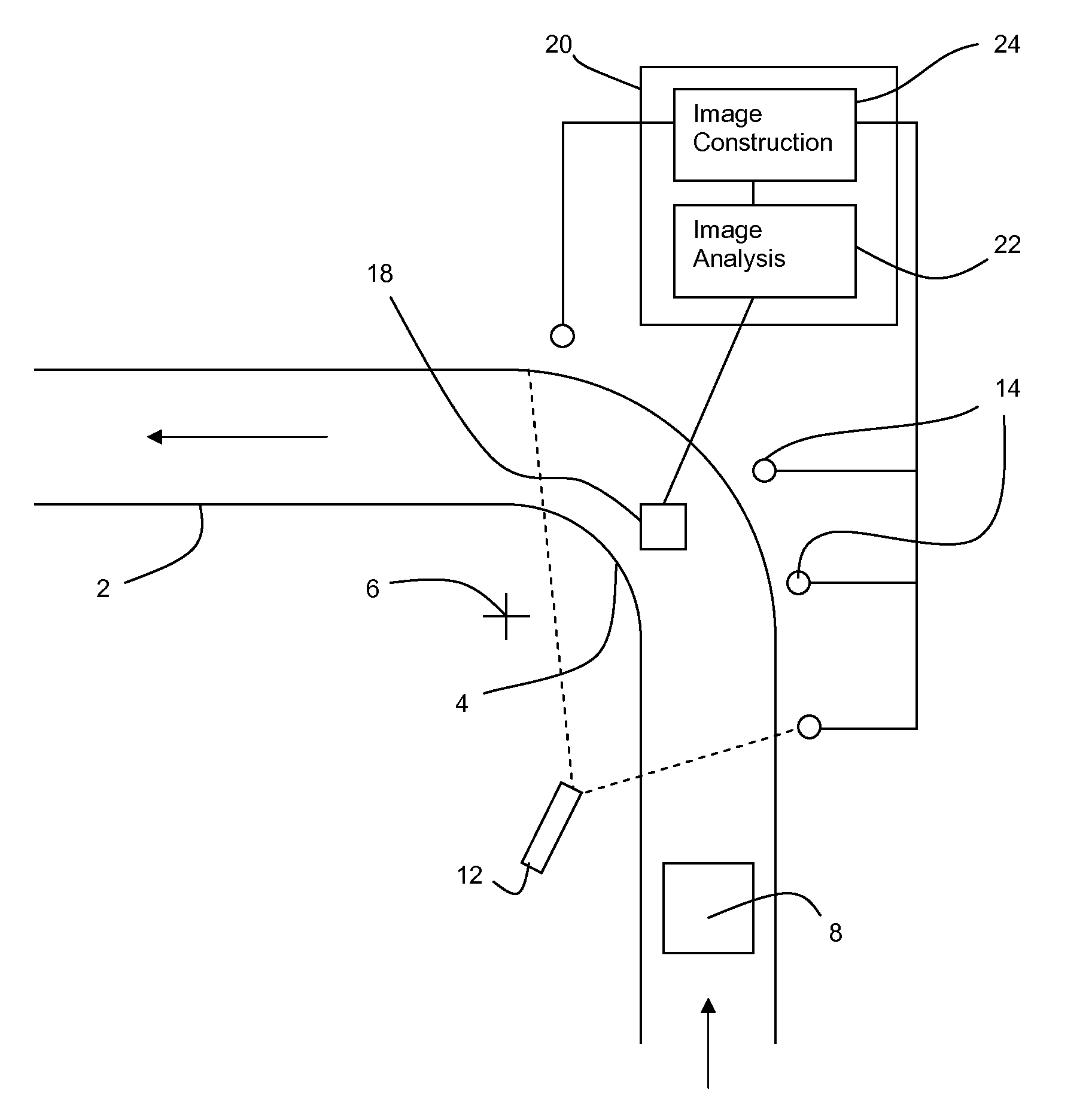
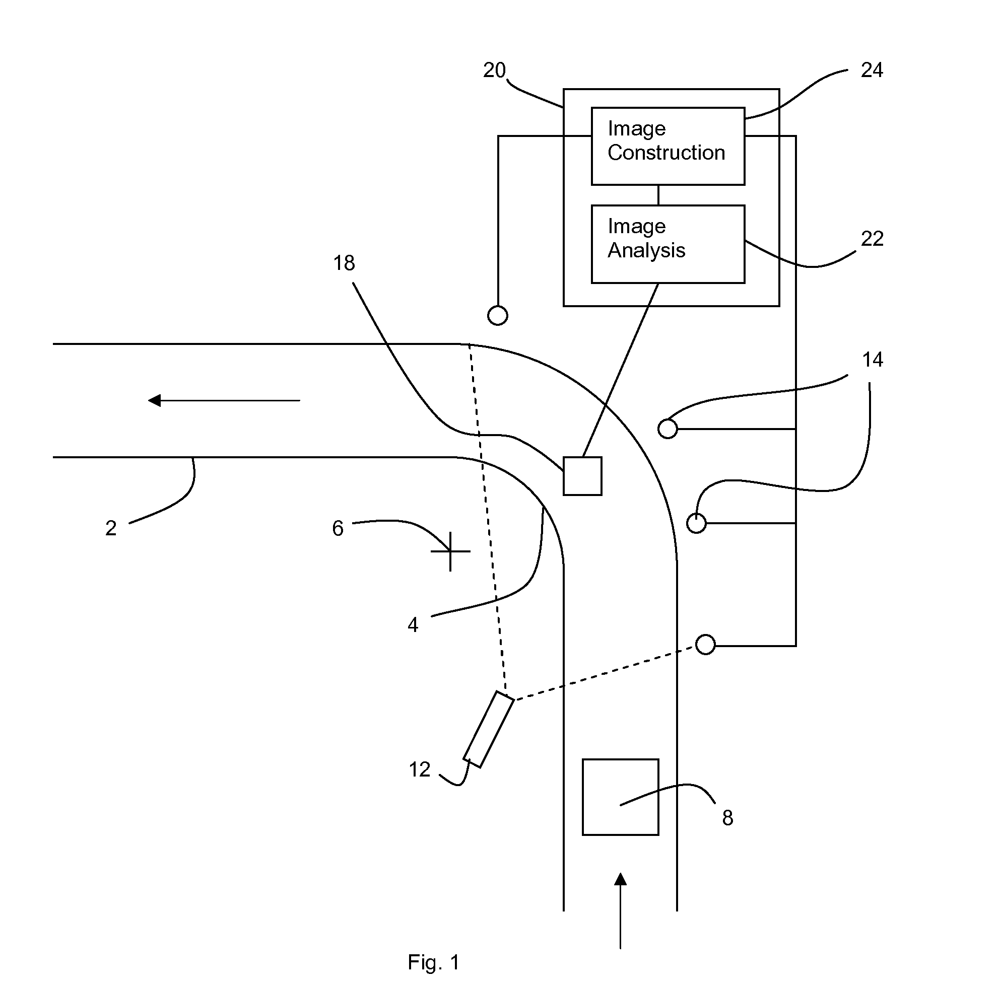
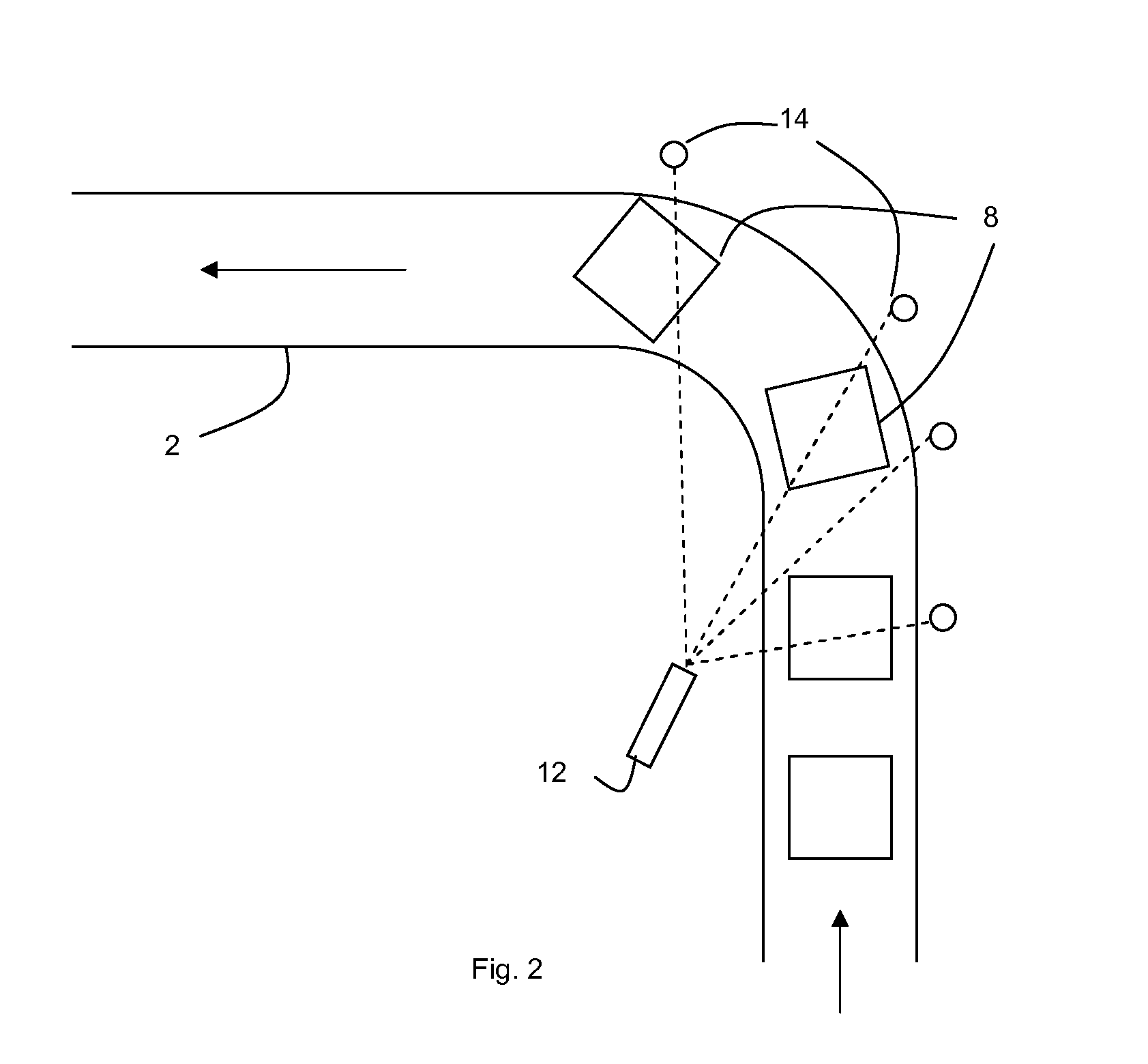
[0017]A baggage conveyor 2 of the type used to carry baggage 8 in an airport or other facility takes baggage along a predetermined path. Such paths are almost never exactly straight and pre-existing baggage conveyors thus typically include several bends or corners 4.

[0018]A baggage inspection system 10 is mounted at a corner 4 along the conveyor. A 90° corner is selected in the embodiment described since such corners frequently occur. Thus, it is generally possible to locate the baggage inspection system 10 around a pre-existing corner in baggage conveyors. However, it is not essential to use a 90° corner—all that is required is that the motion of the baggage around the corner allows a sufficient variety of images to be captured to carry out the method. A 180° corner is particularly suitable, though it occurs less often. The geometric centre 6 of the corner is indicated.

[0019]The baggage inspection system 10 includes a wide angle X-ray source 12, i.e. without a collimator, which emi...


PUM


Abstract

An X-ray inspection system is mounted around conveyor (2). An X-ray source (12) and a number of X-ray detectors record X-ray images of an object (8) such as baggage moving along the conveyor. A visual recordal system (18,22) tracks the motion of the object along the conveyor to identify the location and orientation of the object as it moves along the conveyor. A tomosynthesis image of the object is calculated from the plurality of X-ray images using the location and orientation information from the visual recordal system.

Description

[0001]The invention relates to X-ray scanning and in particular to X-ray scanning which uses multiple plane images to generate a three-dimensional representation of an object. The invention may be used in particular in the field of baggage scanning.[0002]Typical baggage scanning of bags at airports uses a primary X-ray scanner located on a baggage transport system that draws baggage through the X-ray scanner continuously. Baggage is scanned by X-ray, essentially scanning a 2 dimensional slice through the baggage. The operator identifies and separates a small percentage of baggage for further secondary scanning and allows the rest to pass through.[0003]Secondary scanning can take place using a number of different technologies.[0004]However, typically secondary scanning takes place on single items of baggage that are not on a conveyor, but which may be loaded into a machine and are stationary during secondary inspection. This allows the use of more advanced and accurate inspection tec...

Claims


Application Information

Patent Timeline
IPC IPC(8): G01N23/04
CPCG01T1/1603
Inventor SPELLER, ROBERTREID, CAROLINE
Owner UCL BUSINESS PLC
Learn More