Automatic calibration systems and methods of use

a technology of automatic calibration and calibration system, which is applied in the direction of instruments, catheters, diagnostic recording/measuring, etc., can solve the problems of time-consuming methods and operator errors,

Active Publication Date: 2012-09-06
VOLCANO CORP
View PDF10 Cites 122 Cited by
  • Summary
  • Abstract
  • Description
  • Claims
  • Application Information

AI Technical Summary

Benefits of technology

[0005]The invention addresses the above-identified problems and relates to automatic calibration. A catheter can be calibrated, according to the invention, by taking an image in a catheter and utilizing a template to identify the position of the catheter reflection lines. Another way to calibrate a catheter is to image a catheter pullback, align the image data to ensure any shif

Problems solved by technology

This method can be time consuming

Method used


Image

  • Automatic calibration systems and methods of use
  • Automatic calibration systems and methods of use
  • Automatic calibration systems and methods of use

Examples


Embodiment Construction

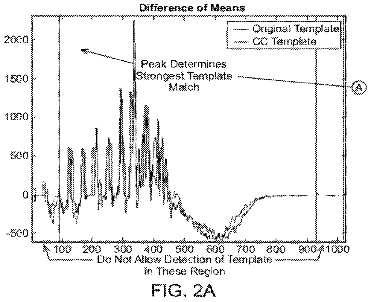
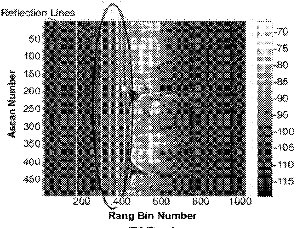
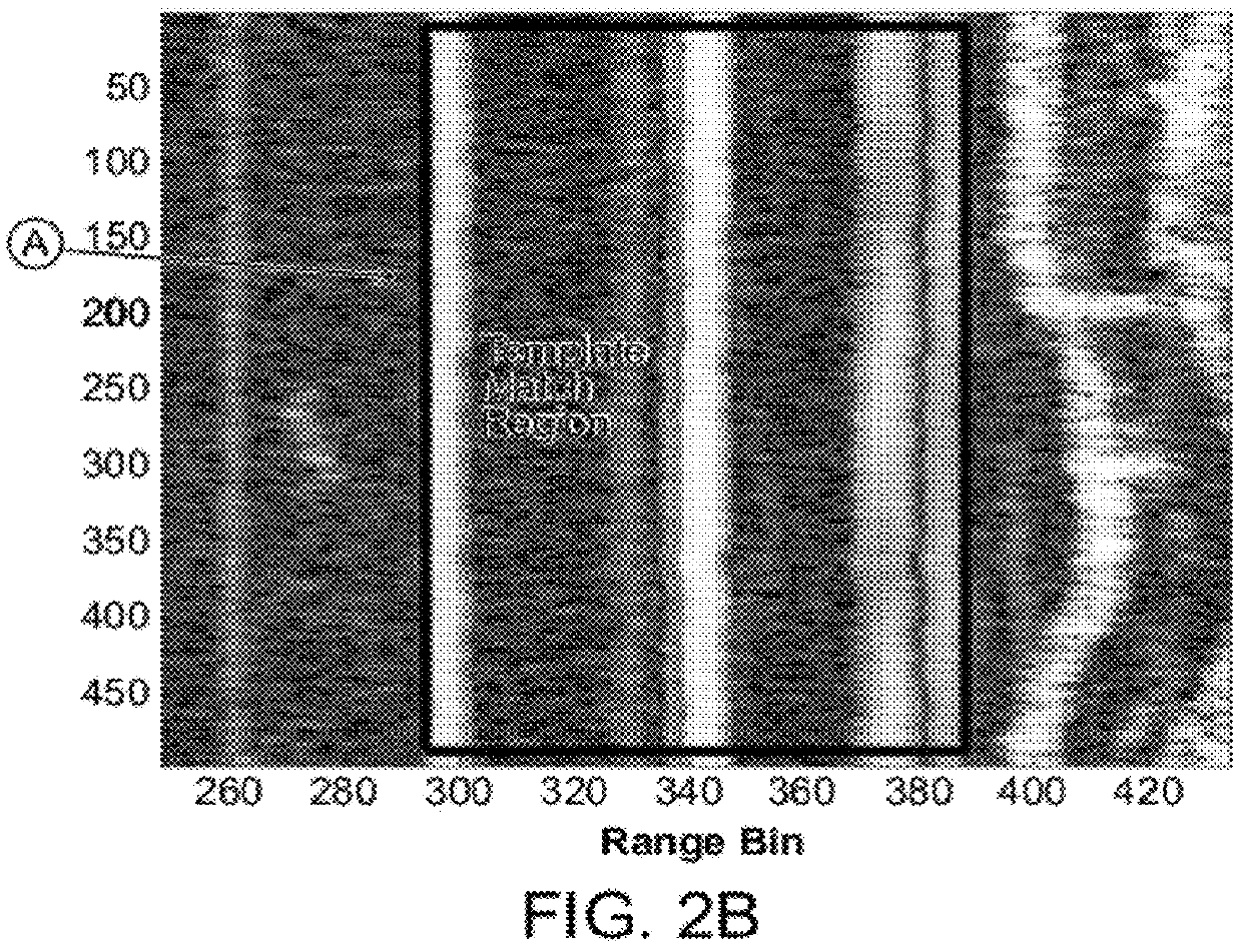
[0035]In general, automatic calibration systems and methods according to the invention provide a repeatable way of detecting the internal catheter reflections and shifting the internal catheter reflections to calibrate an image. In one embodiment, the internal catheter reflections comprise reflections due to the end of the fiber optic cable, minor, lens, sheath, fluids, biological vessels, or any other objects that cause reflections and the like. The internal catheter reflections can be shifted mechanically and / or digitally. Generally, the automatic calibration comprises a first mode, a second mode, and a third mode. The calibration systems and methods update and maintain the calibration on a continuous frame-by-frame basis after an initial calibration.

[0036]An Optical Coherence Tomography (OCT) system may include a Fourier domain OCT (“FD-OCT”), sometimes known as Spectral Domain OCT (“SD-OCT”), or a Time-Domain OCT scanning (“TD-OCT”), where the optical path length of light in the...


PUM


Abstract

The disclosed automatic calibration systems and methods provide a repeatable way to detect internal catheter reflections and to shift the internal catheter reflections to calibrate an image.

Description

CROSS-REFERENCE TO RELATED APPLICATIONS[0001]This is a continuation-in-part of U.S. patent application Ser. No. 13 / 249,339, which was filed Sep. 23, 2011, which is a continuation of Ser. No. 12 / 172,980 (U.S. Pat. No. 8,049,900), which was filed Jul. 14, 2008 and which claims priority to U.S. patent application Ser. No. 60 / 949,467 filed Jul. 12, 2007, and the entirety of each of which is incorporated herein by reference.FIELD OF THE INVENTION[0002]The invention generally relates to calibration systems and methods of use, and more particularly to calibration systems for optical imaging systems.BACKGROUND[0003]Accurate Optical Coherence Tomography (OCT) measurements or dimensional analysis require the displayed tomographic image to correctly represent physical space (i.e. conversion from image pixels to physical mm). This requirement is complicated by factors such as varying object refractive indexes (catheter optics, sheath, lumen, tissue) and the arbitrary location (in z) of relevant...

Claims


Application Information

Patent Timeline
IPC IPC(8): G06K9/62
CPCG01B9/02004G01B9/02057A61B5/6852A61B5/0066A61B5/0073A61B5/0084G01B2290/25G01B9/02091G01N21/274G01N21/4795A61B5/7257G01B9/02069G01B9/02083G01M11/31
Inventor KEMP, NATHANIEL J.BEGIN, ELIZABETHELMAANAOUI, BADR
Owner VOLCANO CORP
Why Eureka
Try Eureka