Pump for Immersion Within a Fluid Reservoir

a technology of fluid reservoir and pump, which is applied in the field of pumps, can solve the problems of achieve the effects of improving pump efficiency, allowing variation in length, and reducing pressure drop and efficiency loss

Active Publication Date: 2012-09-06
NUHN INDS
View PDF4 Cites 14 Cited by
  • Summary
  • Abstract
  • Description
  • Claims
  • Application Information

AI Technical Summary

Benefits of technology

[0009]The pump body and fluid conduit may be extensible along a longitudinal axis of the pump in order to vary a length of the pump. This permits further flexibility in terms of pump position relative to the reservoir surface and allows the pump housing to be extended downwardly towards the surface as the reservoir is emptied. The pump may comprise a drive means for delivering motive power from a motive power source (such as an engine located, for example, on the tractor), to the impeller of the pump. The drive means may be adapted for adjustment with the pump body along the longitudinal axis. The drive means may comprise a hydraulic fluid conduit for providing hydraulic fluid power to a hydraulic motor connected to the impeller or, preferably, a Power Take-Off (PTO) shaft that is extensible with the pump body and fluid conduit. The pump body, fluid conduit, and drive means may comprise telescoping connections to permit variation in length.
[0010]The housing desirably improves efficiency of the pump by directing the fluid not just tangentially of the housing, but also upwardly. This eliminates the need for elbows to direct the fluid upwardly, which lead to pressure drop and efficiency loss. The outlets desirably direct the fluid upwardly from the housing at an angle of from 20 to 70 degrees relative to a plane of rotation of the impeller, more desirably at an angle of from 30 to 60 degrees, yet more desirably at an angle of from 40 to 50 degrees. The at least two outlets may comprise at least three outlets or at least four outlets. The at least two outlets may comprise, two outlets, three outlets or four outlets. The outlets may be evenly spaced about the circumference of the housing.
[0011]In order to impart the desired direction to the fluid as it leaves the housing and to reduce the amount of energy robbing directional change required, it is desirable that the vanes of the impeller are configured to direct the fluid both tangentially and upwardly, relative to the plane of rotation of the impeller, within the housing. This can be accomplished by providing the vanes with a curved side profile, such that rotation of the impeller causes the fluid to follow the curvature of the vane and directs the fluid tangentially to the direction of rotation and upwardly along the vane. This desirably causes the fluid to exit through the outlets in a direction substantially parallel to the outlets, reducing the need for directional change to be imparted to the fluid by the housing and thereby increasing the efficiency of the pum...

Problems solved by technology

This eliminates the need for elbows to direct the flui...

Method used


Image

  • Pump for Immersion Within a Fluid Reservoir
  • Pump for Immersion Within a Fluid Reservoir
  • Pump for Immersion Within a Fluid Reservoir

Examples


Embodiment Construction

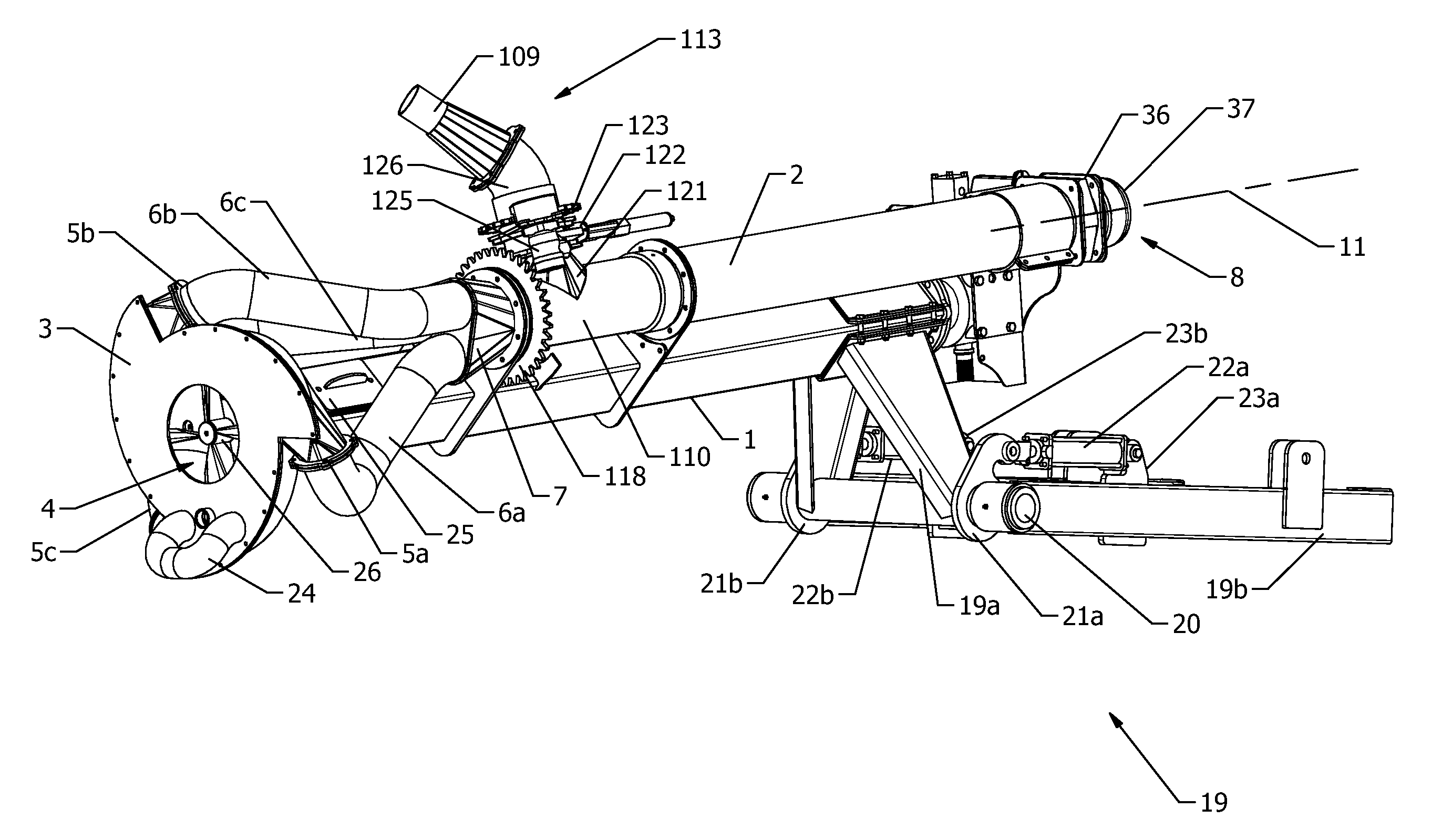
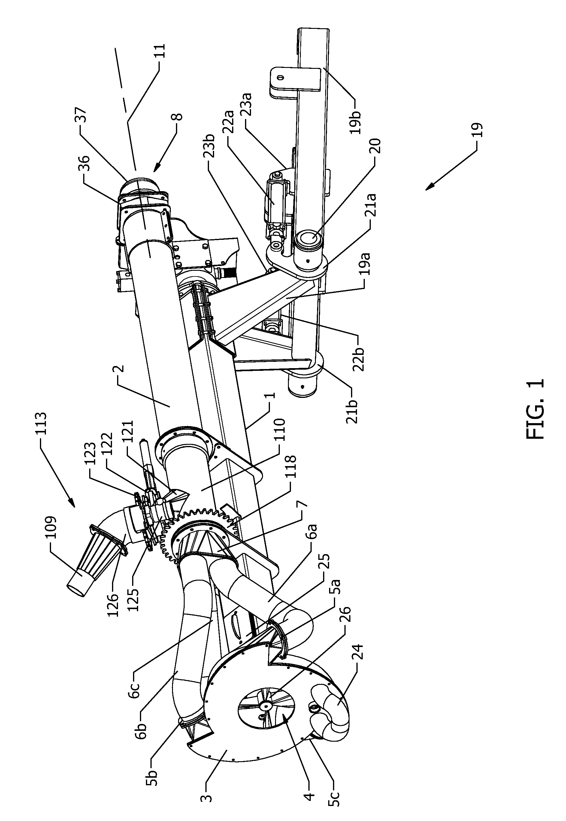
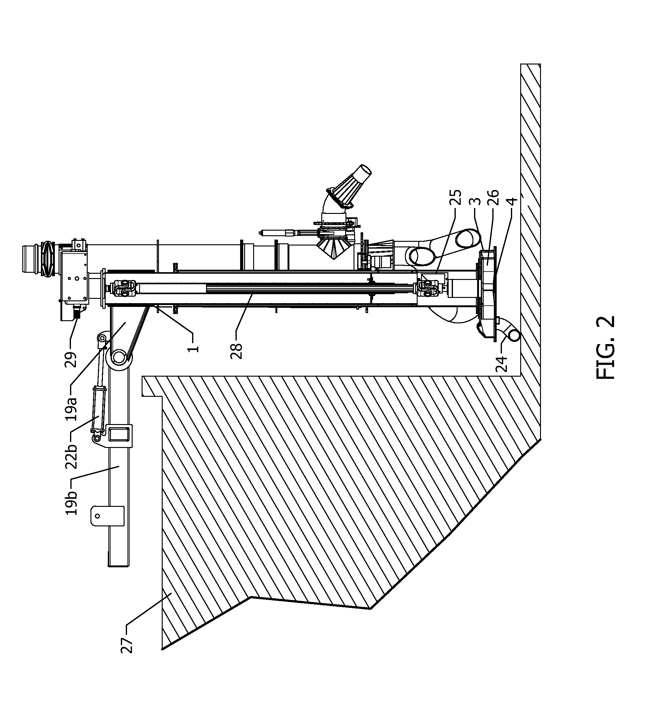
[0032]Referring to FIG. 1, an embodiment of a pump according to the present invention is shown comprising a pump body 1 and an elongated fluid conduit 2 with a centrally located longitudinal axis 11. A pump housing 3 is mounted to a bottom end of the pump body and comprises a fluid inlet 4 located on a bottom thereof and three upwardly oriented tangential fluid outlets 5a, 5b, 5c evenly spaced about the circumference of the housing 3 for directing fluid upwardly along the body 1. The outlets 5a, 5b, 5c are connected to outlet conduits 6a, 6b, 6c that are in turn connected to a fluid combiner 7. The combiner 7 directs the flow from the outlet conduits 6a, 6b into the elongated fluid conduit 2, where it moves upwardly towards the conduit outlet 8. A flow control valve 36, comprising a hydraulically actuated gate valve, is flange mounted at the outlet 8. Fluid exiting the outlet 8 can be delivered to rigid or flexible conduit, depending on what is best suited to the application, attach...


PUM


Abstract

A pump for immersion in a fluid reservoir, such as a pit or lagoon containing liquid manure, from a position at an edge of the reservoir. The pump may be adapted for connection to a farm vehicle, such as a tractor, positioned at the edge of the reservoir. The pump comprises an extensible body, fluid conduit and drive means in order that a length of the pump may be varied in order to accommodate a variety of reservoir fluid heights. In addition, the pump may be pivotable relative to at least a portion of a frame in order that the entrance angle may be adjusted. The pump comprises a bottom housing with a bottom inlet and at least two tangential fluid outlets that are upwardly angled towards the conduit. A combiner is provided to merge the outlets with the fluid conduit. An impeller within the housing is shaped to transfer fluid tangentially and upwardly within the housing to co-operate with the upward angle of the outlets. These features reduce fluid pressure loss and thereby increase fluid flow rate through the pump for a given input power.

Description

FIELD OF THE INVENTION[0001]The invention relates to pumps, particularly pumps that are positionable alongside a fluid reservoir for immersion within the reservoir. In particular, the invention relates to agricultural pumps for the pumping of liquid manure from liquid manure reservoirs.BACKGROUND[0002]Liquid manure from animal husbandry operations, particularly pig farming operations, is typically stored in a large manure reservoir or lagoon until there is a sufficient quantity available to spread or irrigate onto farm land for disposal. In order to remove the manure from the reservoir, a pump is used that is typically located alongside the reservoir and lowered into the reservoir. The pump can be free standing or attached to a tractor, which is often preferable to provide stability to the pump and a source of motive power for the pump.[0003]The volumetric flow rate of fluid handled by the pump is large, typically in excess of 4000 gal / min; accordingly, it is desirable that the pump...

Claims


Application Information

Patent Timeline
IPC IPC(8): F04B53/00F04B39/00
CPCF04D29/607F04D13/08A01C3/026A01C23/045F04D25/0686A01C23/005F04D7/04F04D29/628F04D3/00F04D13/02A01C3/06A01C23/002F04D7/02F04D29/24F04D29/4293F04D29/466
Inventor NUHN, IAN
Owner NUHN INDS
Why Eureka
Try Eureka