Ultrasound diagnostic apparatus, method of transmitting and receiving ultrasonic wave, and program for transmitting and receiving ultrasonic wave

a diagnostic apparatus and ultrasonic wave technology, applied in ultrasonic/sonic/infrasonic diagnostics, instruments, applications, etc., can solve the problems of insufficient consideration of the directionality of the ultrasound scan beam reception beam, significant complex transmission and reception control, etc., to improve the visibility of the puncture needle and increase the intensity of the echo signal

Active Publication Date: 2012-09-06
FUJIFILM CORP
View PDF5 Cites 12 Cited by
  • Summary
  • Abstract
  • Description
  • Claims
  • Application Information

AI Technical Summary

Benefits of technology

[0024]According to the invention, it is possible to increase the intensity of the echo

Problems solved by technology

On the other hand, in the technique described in JP 9-28708 A, with the direction and focal point control of the transmission beam of the ultrasound scan beam, an ultrasonic echo signal of a target line, such as a line of the puncture needle entering the subject, can be intensified, but there is a problem in that transmission and reception control is significantly complicated.
In the technique described in JP 9-28708 A, the directionality of the reception beam of the ultrasound scan beam, or the like is not sufficiently taken into consideration, and there is a problem in that the effect of improving the intensity of the echo signal from the puncture needle is not sufficient.
For example, in the technique described in JP 9-28708 A, there is a problem in that, if the insertion angle of the puncture needle increases, the specular-reflective component of the transmission beam is out of the

Method used


Image

  • Ultrasound diagnostic apparatus, method of transmitting and receiving ultrasonic wave, and program for transmitting and receiving ultrasonic wave
  • Ultrasound diagnostic apparatus, method of transmitting and receiving ultrasonic wave, and program for transmitting and receiving ultrasonic wave
  • Ultrasound diagnostic apparatus, method of transmitting and receiving ultrasonic wave, and program for transmitting and receiving ultrasonic wave

Examples


embodiment 1

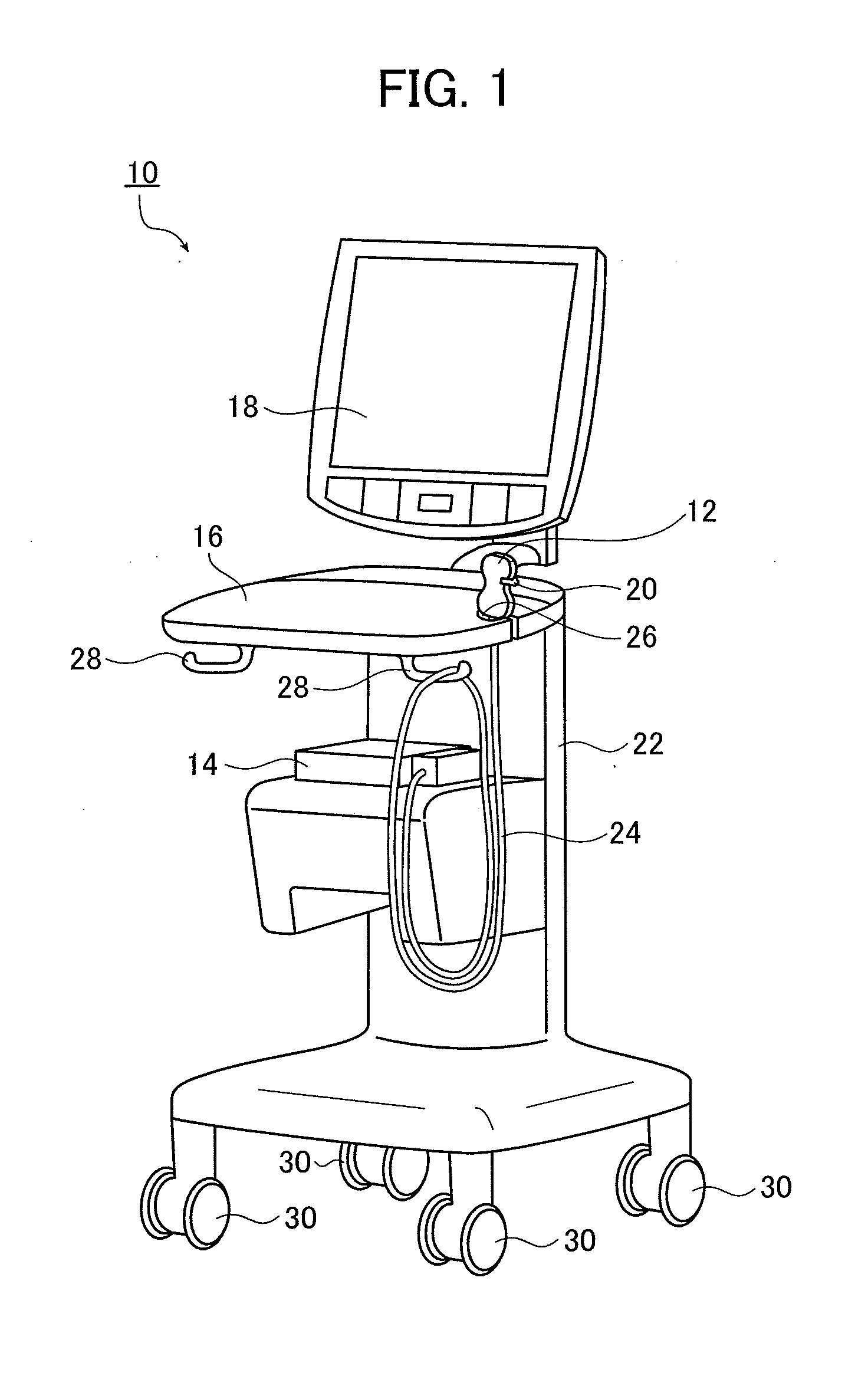
[0038]FIG. 1 is a perspective view showing an example of the main configuration of an ultrasound diagnostic apparatus according to Embodiment 1 of the invention which executes a method of transmitting and receiving an ultrasonic wave according to the invention. Here, a case will be described where an ultrasound probe serving as a probe, an ultrasound diagnostic apparatus body which performs control of the ultrasound probe and analysis of an obtained ultrasonic echo signal, and synthesizes an ultrasound diagnostic image, and a display which displays a synthesized image are separately provided. A puncture adapter is attached to the ultrasound probe.

[0039]As shown in FIG. 1, an ultrasound diagnostic apparatus 10 according to Embodiment 1 of the invention executes a method of transmitting and receiving an ultrasonic wave according to the invention, and includes an ultrasound probe (hereinafter, simply referred to as a probe) 12, an ultrasound diagnostic apparatus body (hereinafter, simp...

embodiment 2

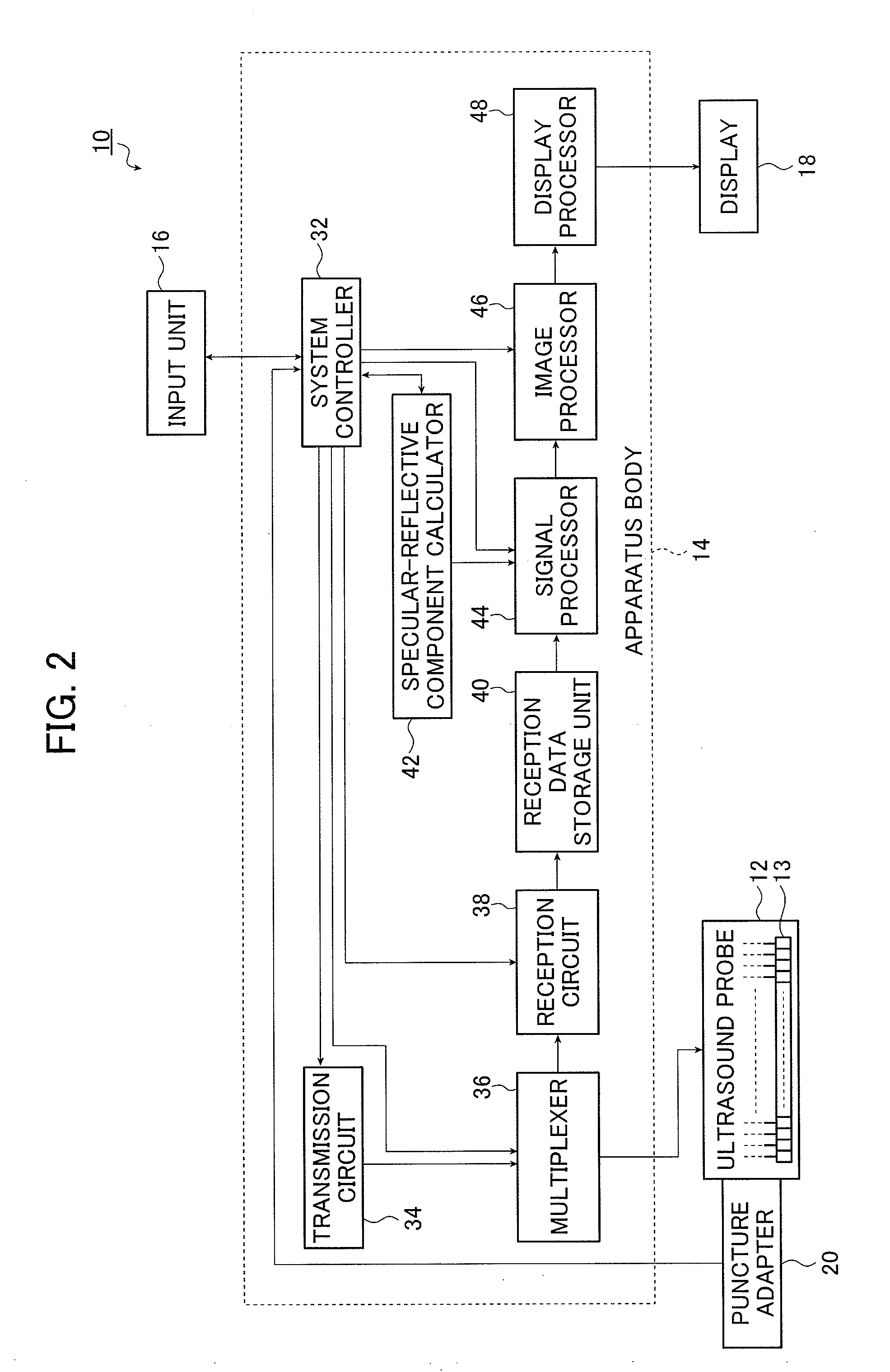
[0096]An ultrasound diagnostic apparatus according to Embodiment 2 of the invention has a reception apodization function added to the signal processor 44 of the apparatus body 14 of the ultrasound diagnostic apparatus 10 in Embodiment 1. The configuration of the ultrasound diagnostic apparatus of this embodiment is substantially the same as the ultrasound diagnostic apparatus 10 shown in FIGS. 1 and 2, except the reception apodization function, and thus description in connection with the drawings will not be provided. Hereinafter, in the detailed description of the ultrasound diagnostic apparatus of this embodiment, the same components as those of the ultrasound diagnostic apparatus 10 shown in FIG. 2 are denoted by the same reference numerals.

[0097]Reception apodization is a technique which gives weighting factors to a plurality of pieces of reception data before an addition process is performed. Specifically, the largest weight is set for a reception signal from an ultrasound tran...

embodiment 3

[0108]An ultrasound diagnostic apparatus according to Embodiment 3 of the invention has an aperture synthesis function different from that of Embodiment 1 added to the apparatus body 14 of the ultrasound diagnostic apparatus 10 in Embodiment 1. The configuration of the ultrasound diagnostic apparatus of this embodiment is substantially the same as that of the ultrasound diagnostic apparatus 10 shown in FIGS. 1 and 2, except that the aperture synthesis function is different, and thus description in connection with the drawings will not be provided. Hereinafter, in the detailed description of the ultrasound diagnostic apparatus of this embodiment, the same components as those of the ultrasound diagnostic apparatus 10 shown in FIG. 2 are denoted by the same reference numerals.

[0109]The aperture synthesis technique for use in this embodiment is the technique which is described in commonly assigned JP 2010-29374 A. Specifically, according to this technique, an ultrasonic beam is transmit...


PUM


Abstract

An ultrasound diagnostic apparatus includes plural ultrasound transducers which perform transmission and reception of ultrasonic waves toward a target site of a subject containing a puncture needle. A method of transmitting and receiving an ultrasonic wave uses the ultrasound transducers. The apparatus and the method form an ultrasonic beam to be transmitted from a transmit aperture set on the ultrasound transducers, acquire information relating to a specular-reflective component of the ultrasonic beam in the puncture needle, set a first receive aperture different from the transmit aperture set on the ultrasound transducers on the basis of the information relating to the specular-reflective component of the ultrasonic beam, and process an ultrasonic echo signal received by the ultrasound transducers using the first receive aperture.

Description

BACKGROUND OF THE INVENTION[0001]The present invention relates to an ultrasound diagnostic apparatus which diagnoses the inside of a subject, such as a human body, using an ultrasound probe having a plurality of ultrasound transducers, a method of transmitting and receiving an ultrasonic wave which transmits and receives an ultrasonic wave from an ultrasound probe to a subject, a program for transmitting and receiving an ultrasonic wave which causes a computer to execute a plurality of steps of the method of transmitting and receiving an ultrasonic wave, that is, a plurality of steps of transmitting and receiving an ultrasonic wave, and a computer readable recording medium having recorded therein the program for transmitting and receiving an ultrasonic wave. In particular, the present invention relates to a technique for allowing paracentesis or the like in which a puncture needle is inserted into a subject while viewing an ultrasound image.[0002]An ultrasound vibrator which is used...

Claims


Application Information

Patent Timeline
IPC IPC(8): A61B8/00
CPCA61B8/0841G01S15/899G01S15/8927A61B8/5253A61B8/4461
Inventor TASHIRO, RIKAMIYACHI, YUKIYAKATSUYAMA, KIMITO
Owner FUJIFILM CORP
Why Eureka
Try Eureka