
Method and injection molding machine having a modular structure

a technology of modular structure and injection molding machine, which is applied in the direction of metal-working equipment, metal-working equipment, manufacturing tools, etc., can solve the problems of uneconomical expenses, inability to withstand longitudinal connections, and complex handling and logistics, and achieve the effect of more economical

Inactive Publication Date: 2012-09-13
NETABTAL MASCHEN
View PDF1 Cites 2 Cited by
  • Summary
  • Abstract
  • Description
  • Claims
  • Application Information

AI Technical Summary

Benefits of technology

The invention is a new type of injection molding machine that is designed to be modular. This means that the machine is made up of different parts that can be easily assembled and connected together. The parts are standardized, meaning that they have standardized interfaces that allow for easy assembly. This new design has several advantages over conventional machines. First, it allows for the separation of the mold clamping and injection unit sides, making it easier to assemble and transport the machine. Second, it allows for the use of different manufacturers for the different parts, reducing costs and simplifying logistics. Third, it allows for the use of both electric and hydraulic drives, making it more flexible and efficient. Fourth, it allows for the quick definition and realization of customer orders. Fifth, it reduces processing time and increases the number of pieces in production. Overall, the new design offers a more efficient and flexible solution for injection molding machines.

Problems solved by technology

Handling and logistics are then also complex, because the same company must process several concepts.
Such longitudinal connections would be unable to withstand, when transported as a single piece, handling, such as lifting with a crane, or moving or placing the machine on uneven support surfaces.
Upon closer scrutiny, some expenses are uneconomical.
There is a risk for a company to limit itself to only a single type or a standard line of a single injection molding machine type, because market demand, for example in relation to machines for producing pre-forms, for optical disk manufacture, or the manufacture of other injection molding machines, for example for the producing consumer goods or packaging components, is subject to severe variations.
In this way, identical lines of products can be used and assembled for machines of types and sizes, which has thus far not been possible.

Method used


Image

  • Method and injection molding machine having a modular structure
  • Method and injection molding machine having a modular structure
  • Method and injection molding machine having a modular structure

Examples


Embodiment Construction

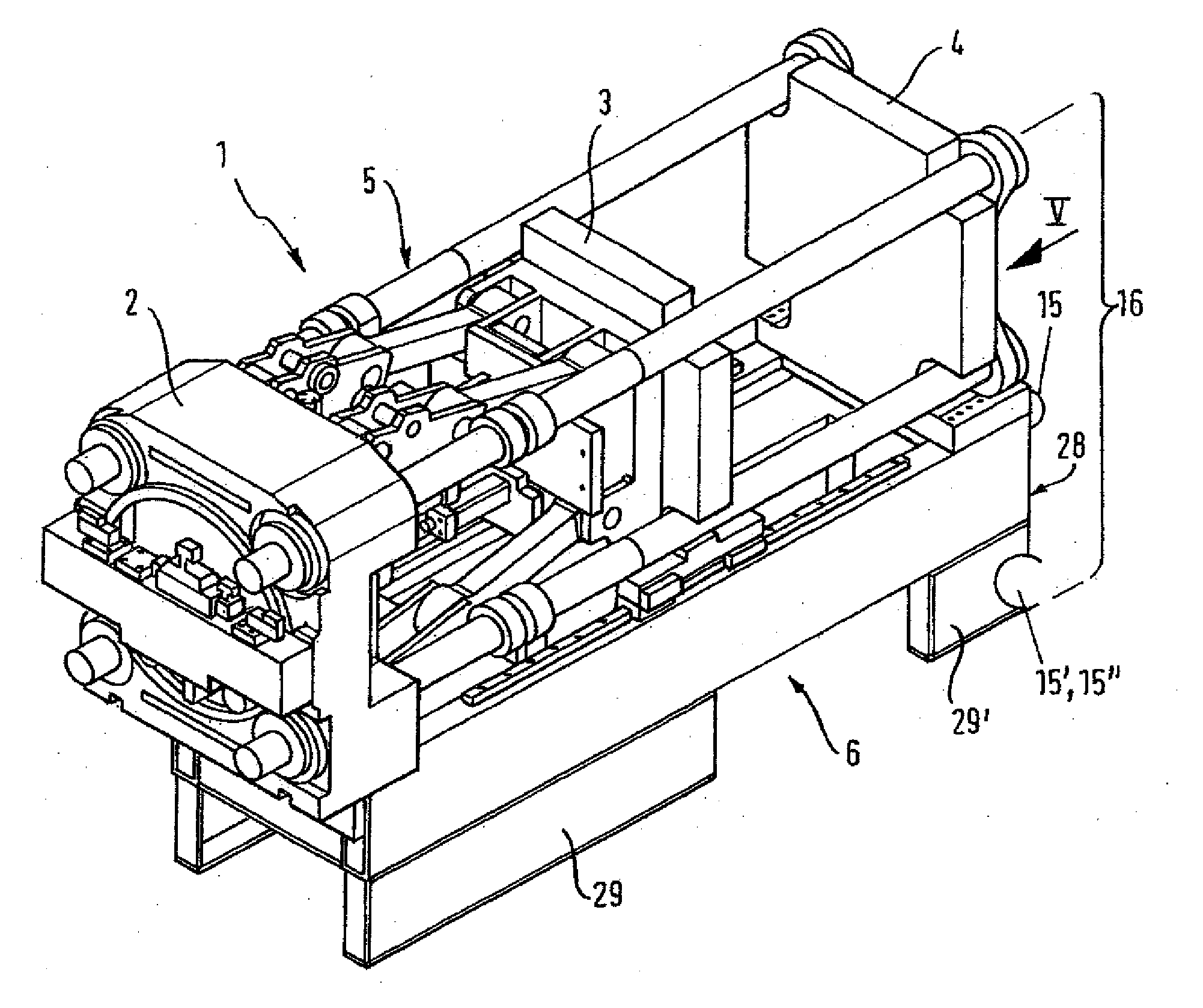
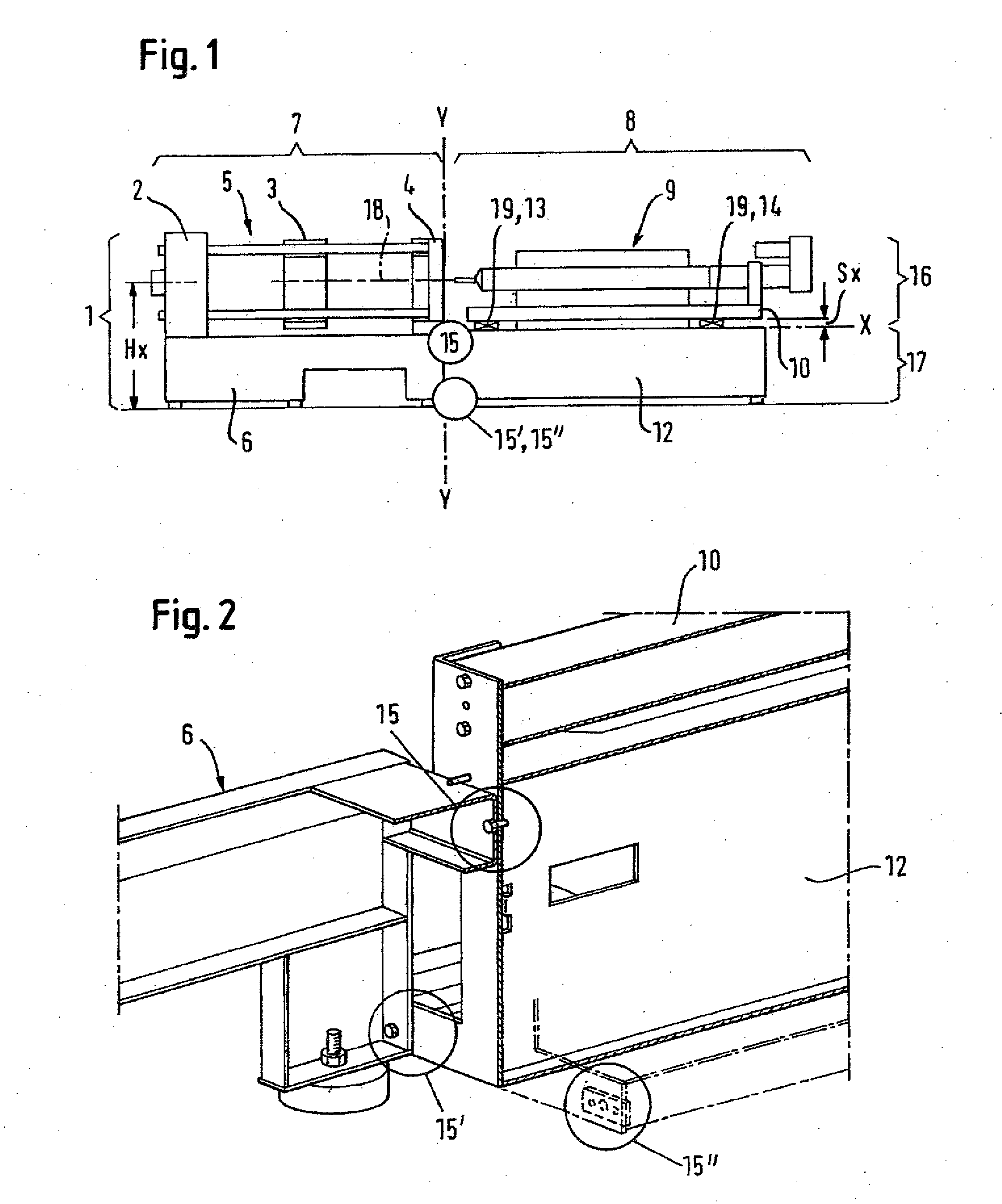
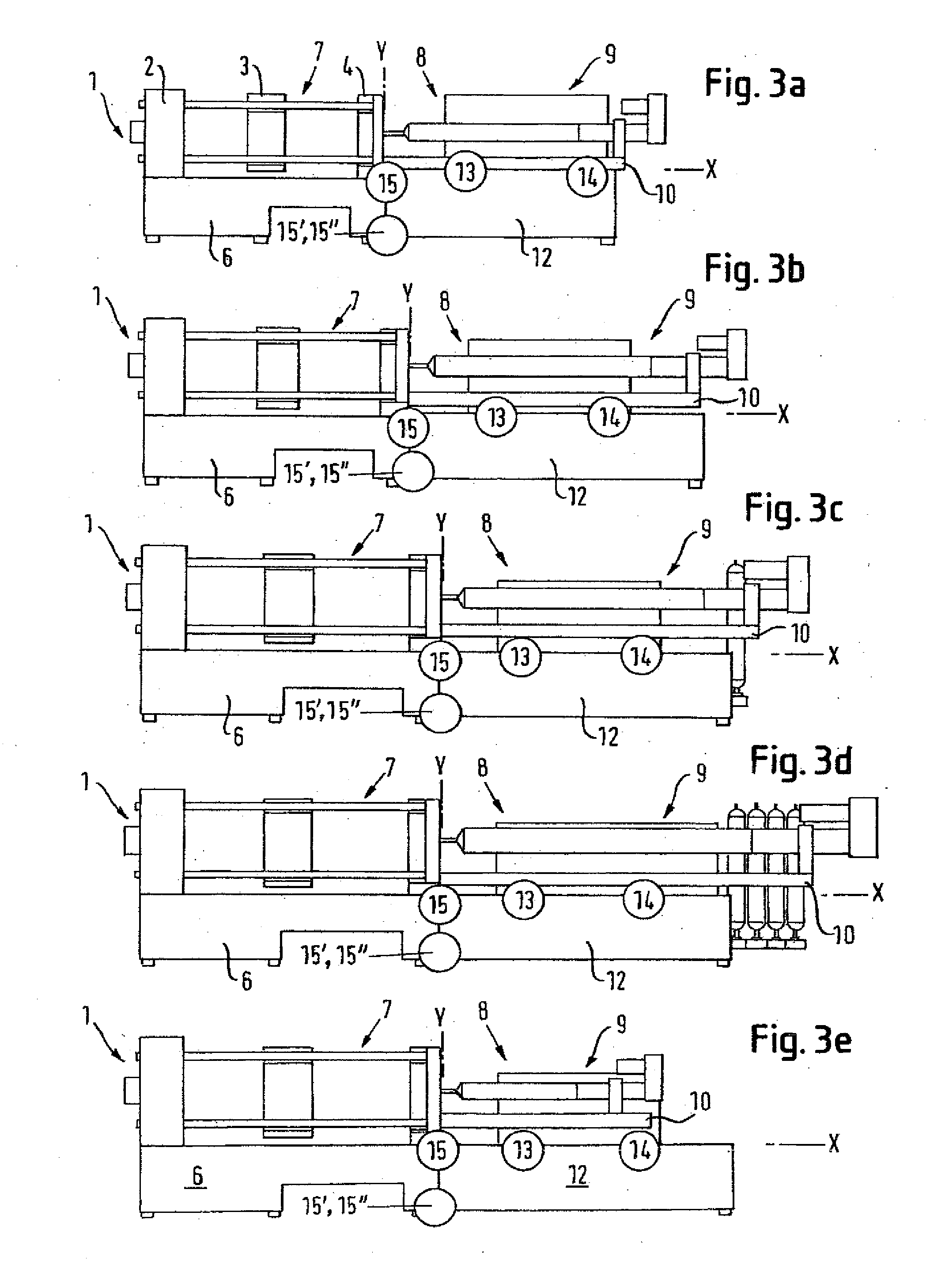
[0060]Reference is made hereinafter to FIGS. 1 and 2. FIG. 1 shows the main separation plane Y-Y between the mold clamping side 7 and the injection unit side 8, and also the separation plane X between the injection unit module 16 and the drive module 17. The exact height position Hx is determined when the mold clamping module 1 is defined, which determines both the effective direction of the mold closing force and the corresponding height position for the injection axis 18. Because the injection module substructure 12 and the injection unit 9 themselves have standardized height dimensions, height differences Sx are compensated by spacers 19.

[0061]FIG. 2 shows the main interfaces 15, 15′, 15″ between the mold clamping side 7 and the injection unit side 8, and between the mold clamping bed 6 and the injection module substructure 12. The massive coupling interfaces 15, 15′ and 15″ of the two machine bed halves make it possible to transport the machine as a single unit. The coupling int...


PUM

PropertyMeasurementUnit
weightaaaaaaaaaa
weightaaaaaaaaaa
sizesaaaaaaaaaa

Abstract

A method for assembly of injection molding machines of different sizes constructed in modular form at a machine manufacturer and for transport of such modular injection molding machines to an installation site. The mold clamping side and the injection unit side are assembled during final assembly at the installation site of the complete injection molding machine by connecting the mold clamping module with the injection module or with a drive module by way of the standardized upper and lower assembly or coupling interfaces of the mold clamping side and the injection unit side, so as to form a one-piece injection molding machine having a bending-resistant substructure.

Description

CROSS-REFERENCES TO RELATED APPLICATIONS[0001]This application is a division of prior filed copending U.S. application Ser. No. 12 / 441,473, filed Mar. 16, 2009, which in turn is the National Stage of International Application No. PCT / EP2007 / 007928, filed Sep. 12, 2007, which designated the United States and has been published as International Publication No. WO 2008 / 031574 and which claims the priority of Swiss Patent Application, Serial No. 2006 01486-06, filed Sep. 14, 2006, pursuant to 35 U.S.C. 119(a)-(d).[0002]The contents of U.S. application Ser. No. 12 / 441,473, International Application No. PCT / EP2007 / 007928, and Swiss Patent Application, Serial No. 2006 01486-06 are incorporated herein by reference in their entireties as if fully set forth herein.TECHNICAL FIELD[0003]The invention relates to a method for logistics, the configuration and the structure of injection molding machines at the machine manufacturer, in particular for the production and the transport of injection mol...

Claims


Application Information

Patent Timeline
Patent Type & Authority Applications(United States)
IPC IPC(8): B23P17/04
CPCB29C45/03B29C45/1761B29C45/46Y10T29/49826B29C2045/1765B29C2045/1767B29C45/64
Inventor WENZIN, PLACIJENNY, DANIELWEINMANN, ROBERT
Owner NETABTAL MASCHEN
Learn More