Automatic Traction Device

a technology of traction device and traction element, which is applied in the direction of non-skid devices, wheels, vehicle components, etc., can solve the problems of traction element impact and deflection, damage to the traction element or the traction device body, eventual failure, etc., to prevent damage to the device and its components, and permit non-destructive elastic deflection

Inactive Publication Date: 2012-09-13
KAHEN SOLEYMAN +1
View PDF4 Cites 12 Cited by
  • Summary
  • Abstract
  • Description
  • Claims
  • Application Information

AI Technical Summary

Benefits of technology

[0018]The present invention is directed to a novel automatic traction device for preventing damage to the device and its components, as well at surrounding objects and people due to tire-roadway interaction forces. The present invention provides a means to elastically couple the traction assembly to the traction device to permit nondestructive elastic deflection

Problems solved by technology

If the tire, with the traction elements extended thereover, encounters rough road conditions or potholes, the traction elements can be resultantly impacted and deflected due to the impact forces.
If the traction element is rigidly coupled to the body of the automatic traction device, a substantial deflection could cause damage to the traction element or the traction device body, or both.
Even repeated smaller deflections can cause fatigue and eventual failure over time or given life cycle.
A large deflection could potentially damage parts of the traction device, such as the gearing, motor and other internal parts.
A large enough deflection could also shear the traction element, causing it to fly off the tire with great velocity, having the potential to cause damage to cars or people.
Therefore, traction device failure is undesirable not only for financial reason but also for safety reasons.
Although, the traction devices in the above-mentioned prior art references permit the traction element to extend over the tread area

Method used


Image

  • Automatic Traction Device
  • Automatic Traction Device
  • Automatic Traction Device

Examples


Embodiment Construction

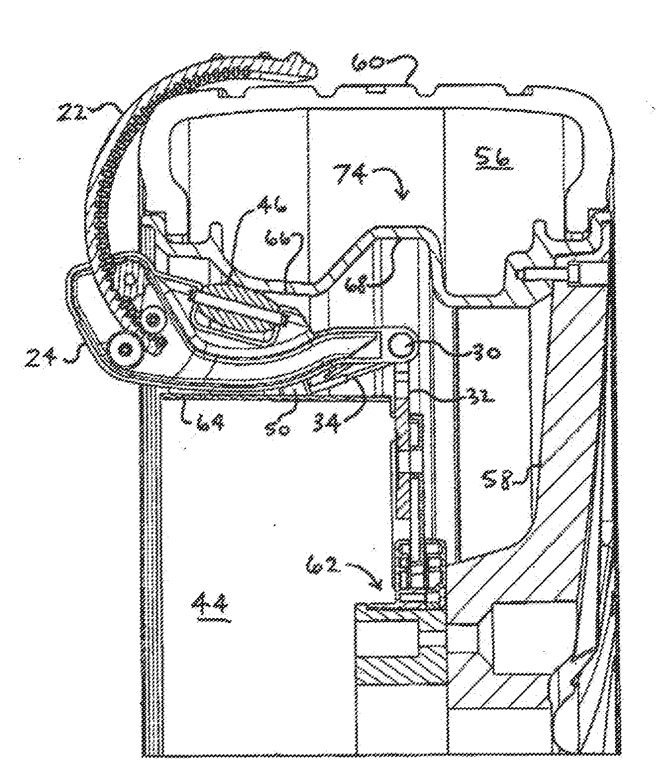
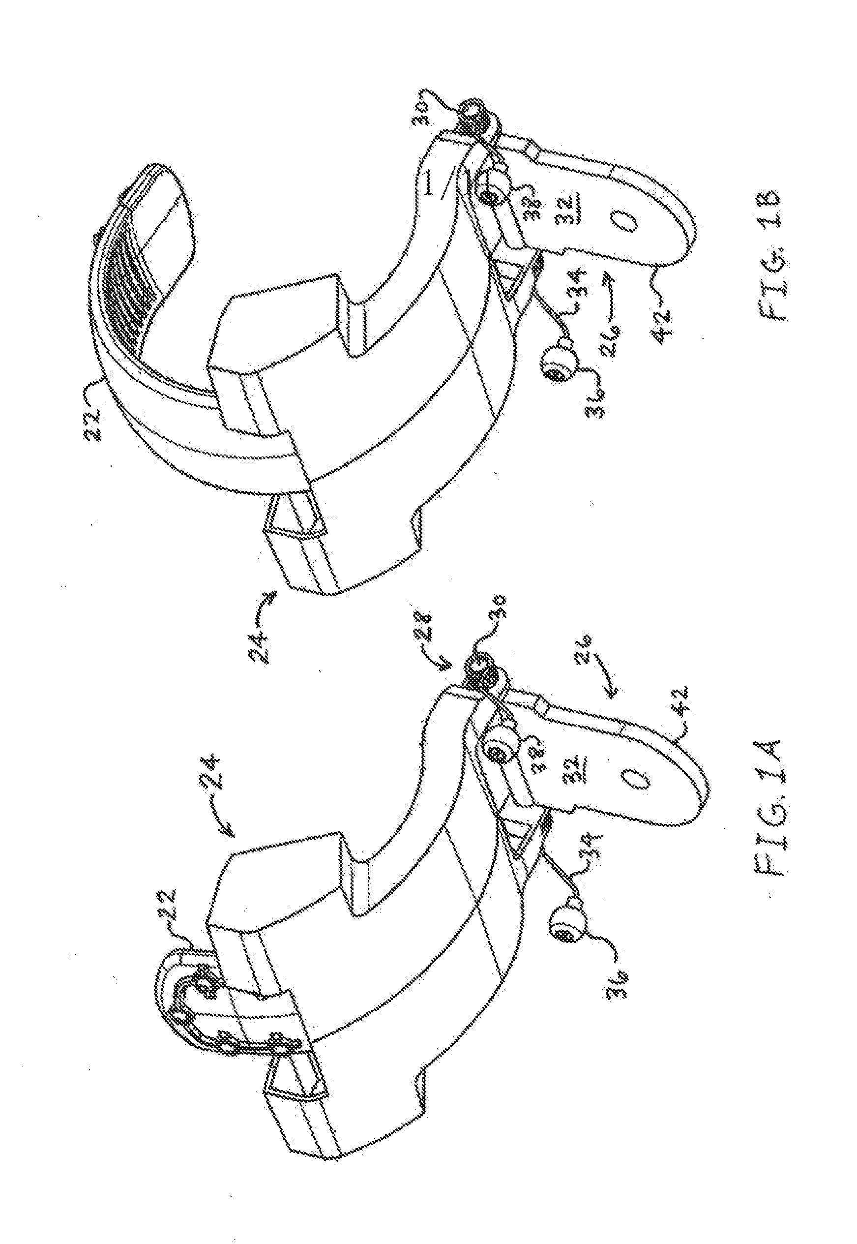
[0099]Looking first at FIGS. 1A and 1B, the traction assembly 24 containing the traction element 22 is shown uninstalled from the traction device 20 and rim for the sake of clarity. FIG. 1A shows the traction element 22 in the retracted mode; and FIG. 1B shows the tractions element 22 in the extended mode. These modes will be described more specifically in the description of FIGS. 5A-B. The preferred embodiment of the resilient coupling means 26 is shown, with the elastomeric leaf 32 attached to the housing 24 through pin 30, which permits rotation of the traction assembly 24 about the pin 30. The biasing means 28 is preferably a torsion spring 34, although other means to bias the traction assembly are available for use. The torsion spring is installed about the pin 30, on both sides, each leg of the torsion spring 34 has attached a ball 36 and 38. The traction assembly 24 is configured to slidably move the traction element 22 through an arcuate path controllably from the retracted ...


PUM


Abstract

The problem of damage sustained to a traction device and the extendable traction elements thereof due to tire-roadway interaction forces exerted on the traction elements while extended over the tire tread area is solved by resiliently coupling a traction assembly within a tire rim to permit movement and repositioning of the traction assembly relative to the rim and biasing back to the original position. Preferably the traction assembly is mounted to a traction hub through a resilient coupling, and with the traction hub permitted to rotate relative to the rim. Also preferably, the invention provides for full retraction and extension of the curved traction elements by use of a linear actuator. The present device delivers increased traction in slippery conditions while protecting the traction device and surrounding mechanics from damage due to the impact of roadway forces, and the device is effectively stowed within the rim when not in use.

Description

RELATED APPLICATION DATA[0001]This application is a continuation-in-part of patent application Ser. No. 12 / 214,608 filed on Jun. 20, 2008, which claims priority to provisional application No. 60 / 936,590 filed on Jun. 21, 2007.BACKGROUND[0002]1. Field[0003]The present invention relates to an automatic traction device to increase traction in snow, ice, or other slippery conditions, and more particularly to a means to protect the traction device from damage due to tire-roadway interaction forces.[0004]2. Description of the Related Art[0005]In snow, ice or other slippery conditions a driver may choose to supplement the traction of a standard tire with snow chains, or preferably a retractable automatic traction device that can be fitted within a rim and configured to extend a plurality of traction elements over the tread area of a tire. Examples of an automatic traction device are disclosed in Kahen U.S. Pat. No. 7,174,935 and Kahen US 2006 / 0096683, the disclosures of which are incorpora...

Claims


Application Information

Patent Timeline
IPC IPC(8): B60C27/02
CPCB60C27/00B60B15/266B60B15/00
Inventor KAHEN, SOLEYMANDIBA, KEYVAN T.
Owner KAHEN SOLEYMAN
Why Eureka
Try Eureka