

Reactor and power converter using the same
a technology of power converter and reactor, applied in the direction of transformer/inductance, magnetic core, core/yoke, etc., can solve problems such as loss in the reactor
- Summary
- Abstract
- Description
- Claims
- Application Information
AI Technical Summary
Benefits of technology
Problems solved by technology
Method used
Image

Examples
first embodiment
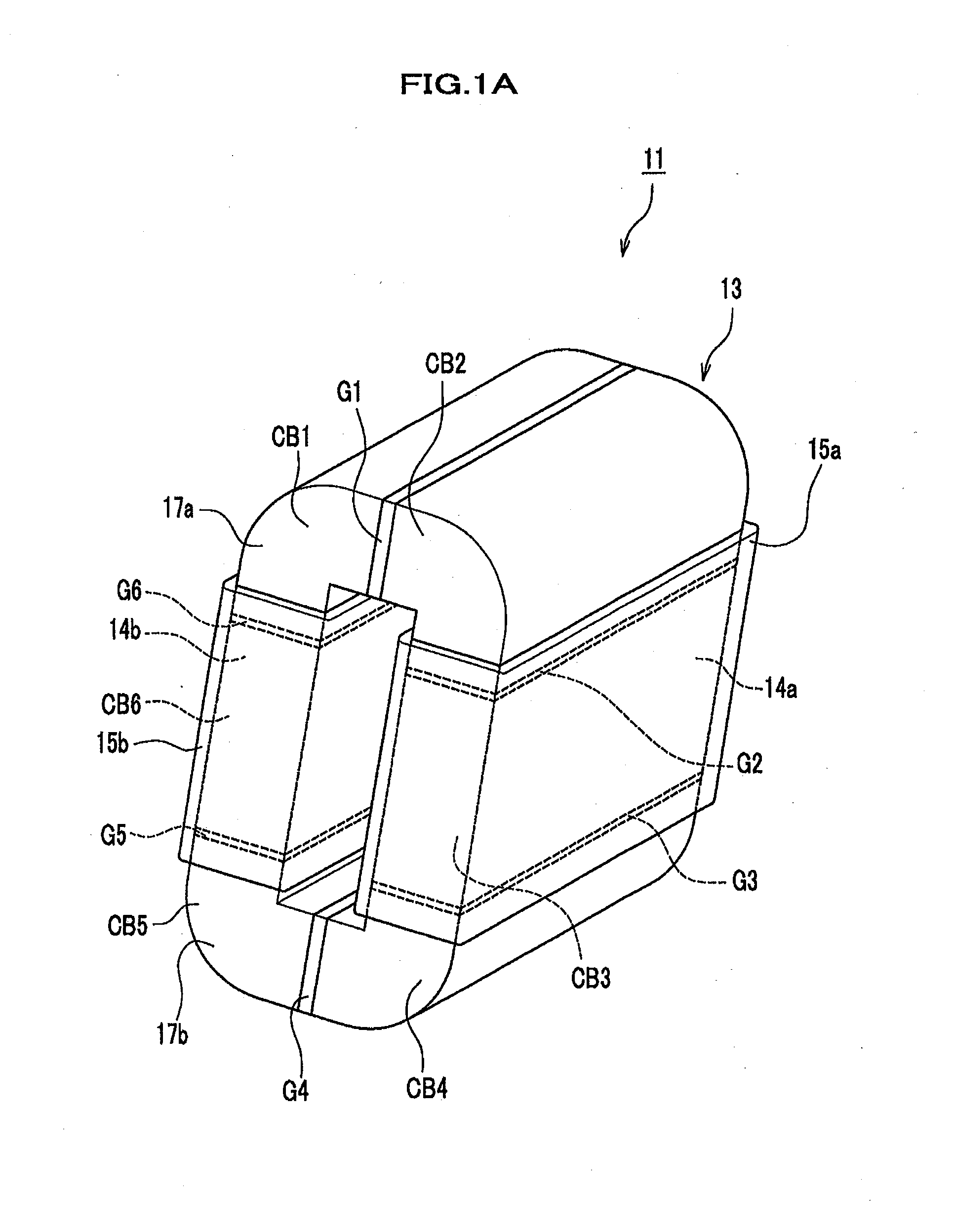
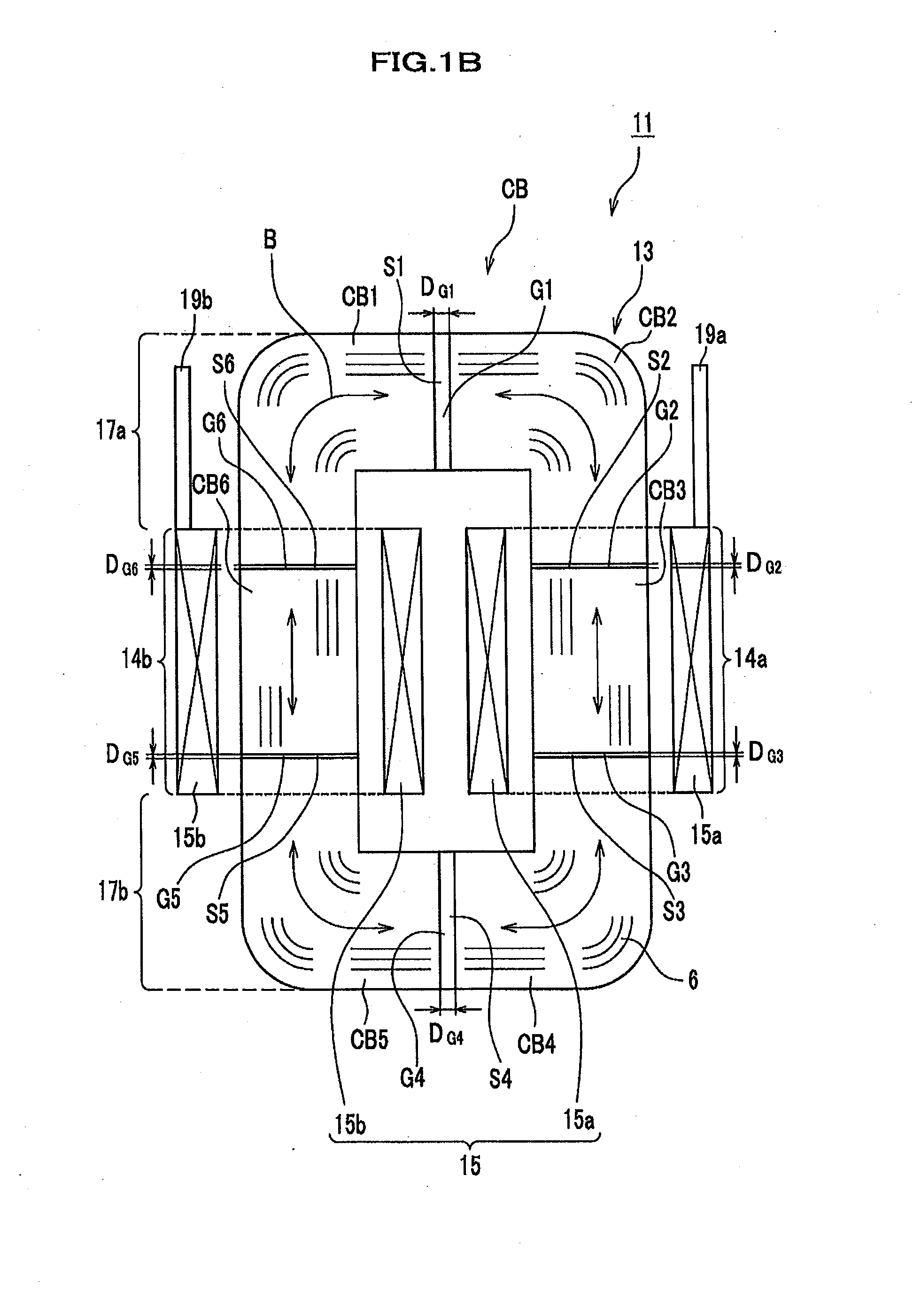
[0027]FIG. 1A shows a perspective view of a reactor according to a first embodiment of the present invention. FIG. 1B is a front cross section view of the reactor according to the first embodiment of the present invention.
[0028]A reactor 11 according to the first embodiment is configured so as to suppress a loss in the reactor 11 caused by leakage of the magnetic flux from gaps G2, G3, G5, G6 even if the gaps G2, G3, G5, G6 are formed within a region where the magnetic excitation coil 15 is wound around a ringed core 13.
[0029]As shown in FIGS. 1A and 1B, the reactor according to the first embodiment includes the ringed core 13 and magnetic excitation coils 15a and 15b wound around parts of the ringed core 13. The ringed core 13 is formed with soft magnetic materials in thin plates 6 which are laminated. More preferably, an isotropic material formed in thin plates may be used. The soft magnetic material is a material having a soft magnetic characteristic (a characteristic of being ea...
second embodiment
[0055]Next, will be described a reactor 21 according to a second embodiment of the present invention. FIG. 2 is a front section view of the reactor 21 according to the second embodiment of the present invention. The reactor 21 has substantially the same configuration as the reactor 11 according to the first embodiment. The same components in the second embodiment as those in the first embodiment are designated with the same or like references and a duplicated description will be omitted.
[0056]There is a difference between the first and the second embodiment as follows:
[0057]Here, positions of the gaps G1 to G6 are expressed using a clock face notation similarly to the first embodiment. The first gap G1 in the first yoke portion 17a is located at a position of 12 o'clock and the forth gap G4 is located at a position of 6 o'clock.
[0058]On the other hand, in the reactor 21 according to the second embodiment, a seventh and tenth gaps G7 and G10 are formed in the first yoke portion 17a a...
third embodiment
[0065]Next, will be described a reactor 31 according to a third embodiment of the present invention. FIG. 3 is a front section view of the reactor 31 according to the third embodiment of the present invention. The reactor 31 has substantially the same configuration as the reactor 11 according to the first embodiment. The same components in the third embodiment as those in the first embodiment are designated with the same or like reference and a duplicated description will be omitted.
[0066]There is a difference between the first and the third embodiments as follows:
[0067]In the reactor 11 according to the first embodiment, the first and second yoke portions 17a, 17b are vertically, in FIG. 1B, divided into two parts across the first and second magnetic leg portions 14a, 14b.
[0068]Positions of the second and third gaps G1 to G6 are expressed using a clock face notation. The second and third gap G2, G3 are located at positions just after and before 3 o'clock with an interval, and the ...
PUM
 Abstract
Description
Claims
Application Information