Apparatus and method for treating a workpiece using plasma generated from microwave radiation

a technology of plasma and workpiece, which is applied in the direction of plasma technique, chemistry apparatus and processes, coatings, etc., can solve the problems of non-uniform and filamentous corona discharge, relatively slow discharge of materials, and localized arcs

Inactive Publication Date: 2005-01-11
THE PROCTER & GAMBLE COMPANY
View PDF28 Cites 283 Cited by
  • Summary
  • Abstract
  • Description
  • Claims
  • Application Information

AI Technical Summary

Benefits of technology

In one embodiment the present invention comprises an apparatus for treating a surface of a workpiece at approximately atmospheric pressure. The apparatus comprises a chamber for containing a plasma, a first inlet having a first inlet orifice for admitting a plasma gas into the chamber, and a microwave power supply for providing microwave radiation. The microwave radiation generates plasma from the plasma gas. The plasma is centered on a plasma core and has an inner plasma zone adjacent the plasma core and an outer plasma zone adjacent the inner plasma zone. The apparatus further has a second inlet having a second inlet orifice for admitting a working gas into the chamber, wherein the working gas generates excited species. The excited species of the working gas does not have deleterious interaction with or caused by the plasma. The apparatus further has an outlet from the chamber, allowing the excited species to exit the chamber and deposit on the workpiece.

Problems solved by technology

However, due to the relatively low energy density, these discharges alter surface properties of materials relatively slowly, if at all.
Also, corona discharges are non-uniform and filamentary in nature.
This may lead to localized arcs known as “hot spots” and non-uniform surface modification.
Generally, the use of corona discharges for treating the surface of a workpiece is unsatisfactory.
If MW plasma is used and the workpiece is too close, it will be damaged by the heat.
Most of this work has been performed in a laboratory environment and has been limited to very small scale operations.
The workpiece is limited to the size of the chamber.
Generally, this will require the chamber to be big, bulky and expensive.
This increased electrode spacing and size constraint creates problems with the generation of uniform plasma.
Furthermore, such a chamber is typically stationary and thus requires the workpiece to be moved and placed within the chamber.
This type of system cannot be used with a stationary workpiece.
Furthermore, these references fail to teach deposition / polymerization / etching, or other surface modifications.
It does not disclose an apparatus or process to plasma treat a workpiece at atmospheric pressure.
However, this system is not designed to treat surfaces.
It is not designed to advantageously admit a working gas into its chamber for the treatment of workpieces.
In addition, this system does not suggest how to get the working gas into the chamber without destroying the working gas by the plasma.

Method used


Image

  • Apparatus and method for treating a workpiece using plasma generated from microwave radiation
  • Apparatus and method for treating a workpiece using plasma generated from microwave radiation
  • Apparatus and method for treating a workpiece using plasma generated from microwave radiation

Examples


example 1

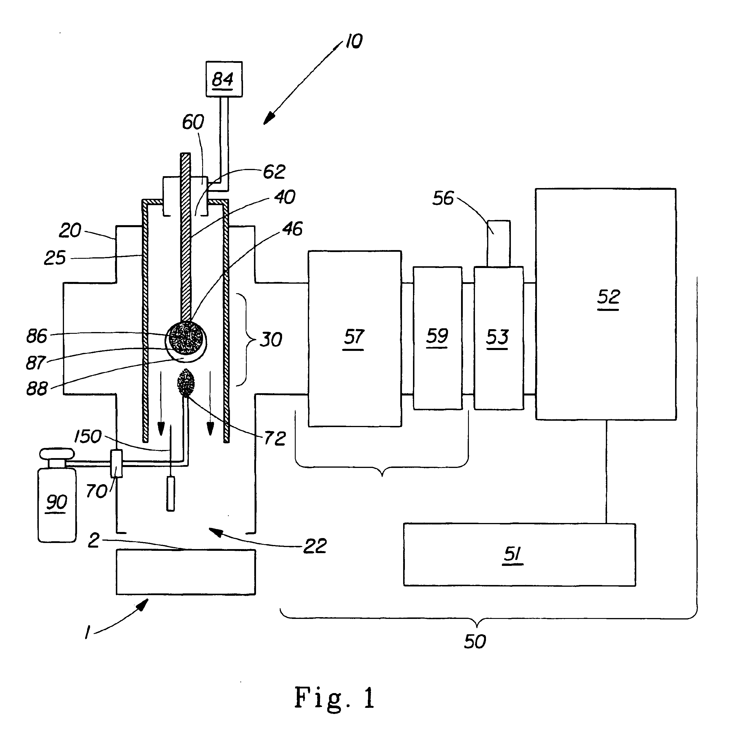
An apparatus 10 identical to the aforementioned MKS / Astex system was provided. Per the manufacturer's directions, Argon plasma gas, 80, was used at the lowest recommended flow rate (14.2 slm) and 500 Watts microwave forward power. The temperatures of the gas containing excited species exiting the chamber were measured at the distances specified in Table 1. The experiment was repeated substituting Helium for Argon as the plasma gas 80 and, significantly, using a flow rate of 3.02 SLM. The results show a drop in the temperature range from 178-370 C for the manufacturer's conditions, to a temperature range of 56-150 C at the lower flow rate. Thus, when the appatatus 10 is operated according to the prior art, the temperature range is too high to treat many common workpieces, 1, such as cotton fabrics. However, when operated in accordance with the present invention, a temperature range suitable for many common workpieces 1 will advantageously result.

Table 1 shows that suitable plasma tem...

example 2

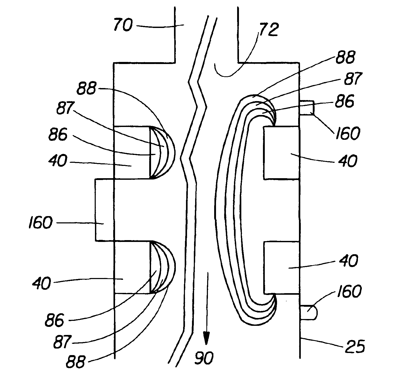
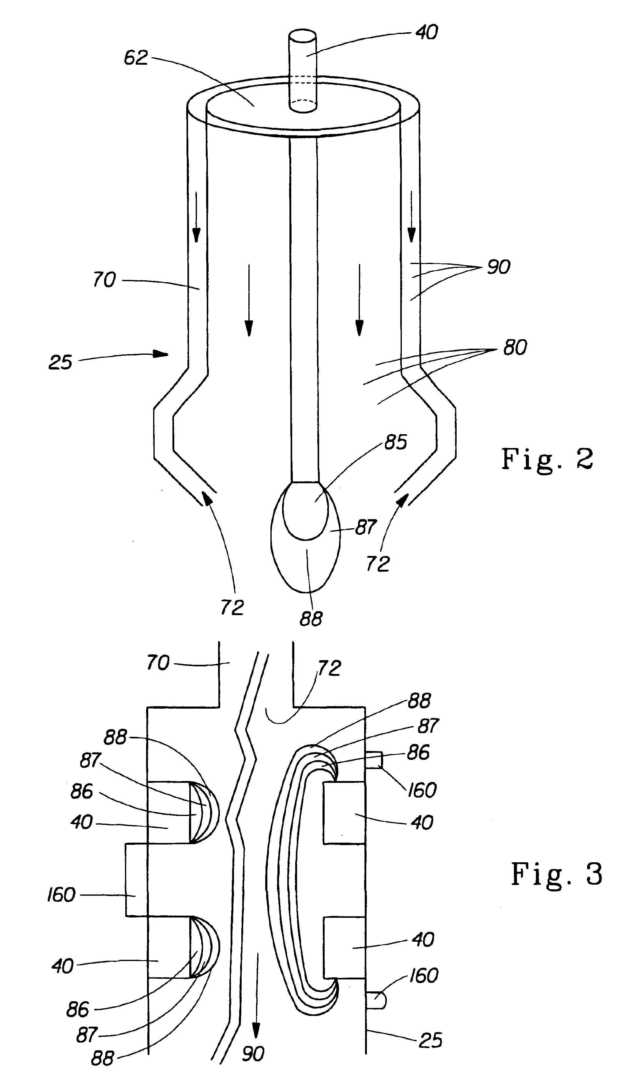
The apparatus of example 1 was used. The plasma gas 80 was Helium. The working gas 90 was perfluormethylcyclohexane (PFMCH) monomer with a carrier gas Argon. In the control experiment, the working gas 90 was introduced to the plasma through a coaxial hole in the ceramic plasma concentrator 40, such that the working gas 90 entered the plasma at the plasma core 86. In the trial the working gas 90 was introduced in a downstream position indicated in Table 2, such that the working gas was believed to be preferentially exposed to the either the outer plasma zone 88 or to excited plasma gas 80 species further downstream thereof. In each case, a piece of 100% cotton fabric was positioned below the outlet 22 in the position indicated in Table 2, such that the working gas 80 and plasma gas 90 impinged on the fabric surface 1 for treatment of the surface 1.

At the end of each trial, the fabric was analyzed for hydrophobicity by placing a water drop on the fabric. Untreated 100% cotton fabric a...

example 3

In a third experiment, the foregoing apparatus 10 was reused and the setup was adjusted as described below. A fabric sample was placed 16 cm from the distal end 46 of the plasma concentrator 40. The plasma gas 80 was Helium and the working gas 90 was PFMCH. The working gas 90 was used with a carrier gas of Helium. The working gas 90 was introduced 3.5 cm downstream of the distal end 46 of the plasma concentrator 40. The treatment time was held constant at 10 minutes and the microwave power varied. The results, shown in Table 3 below, illustrate that the percentage of Fluorine on the sample surface 1 are directly proportional to the MW input power used, throughout the selected power range.

TABLE 3TrialPower (W)Fluorine (percent)1190 3.4220012.5322019.4423034.4


PUM

PropertyMeasurementUnit
pressureaaaaaaaaaa
pressureaaaaaaaaaa
temperaturesaaaaaaaaaa

Abstract

An apparatus and method that generates plasma using a microwave radiation supply. The plasma is used to treat a surface of a workpiece at approximately atmospheric pressure. Plasma excites a working gas to create an excited gaseous species without degradation from undue heat caused by the plasma. The gaseous species exit an outlet of the apparatus to treat the surface of a workpiece when the outlet is juxtaposed with the workpiece.

Description

FIELD OF THE INVENTIONThe present invention relates to an apparatus and method for treating a surface of a workpiece using plasma and more particularly using plasma generated by microwave radiation.BACKGROUND OF THE INVENTIONPlasmas, such as are described herein, are partially ionized gases and consist of ions, electrons and neutral species. Plasma is state of matter produced by the action of DC or AC fields having RF or MW frequencies. Plasmas can be useful for treating the surface of a workpiece.Low power density, low intensity plasmas, such as dark discharges and corona discharges, have been used at low pressure and at one atmosphere for the surface treatment of various materials. However, due to the relatively low energy density, these discharges alter surface properties of materials relatively slowly, if at all. Also, corona discharges are non-uniform and filamentary in nature. This may lead to localized arcs known as “hot spots” and non-uniform surface modification. Generally,...

Claims


Application Information

Patent Timeline
Patent Type & Authority Patents(United States)
IPC IPC(8): H01J37/32H05H1/24
CPCH01J37/32192H05H1/24H01J37/3244H01J37/32357H05H1/46H05H1/463
Inventor SHANOV, VESSELIN NIKOLOVDATTA, SASWATIMIRALAI, SEVED FARHADMCDANIEL, JOHN ANDREW
Owner THE PROCTER & GAMBLE COMPANY
Why Eureka
Try Eureka