Charged particle beam irradiation apparatus and method of irradiation with charged particle beam

Inactive Publication Date: 2000-03-07
MITSUBISHI ELECTRIC CORP
View PDF2 Cites 289 Cited by
  • Summary
  • Abstract
  • Description
  • Claims
  • Application Information

AI Technical Summary

Problems solved by technology

The movement of the bed 27 might be uncomfortable to the patient, and at the same time, there may be an error of position in an irradiate ar

Method used


Image

  • Charged particle beam irradiation apparatus and method of irradiation with charged particle beam
  • Charged particle beam irradiation apparatus and method of irradiation with charged particle beam
  • Charged particle beam irradiation apparatus and method of irradiation with charged particle beam

Examples


embodiment 3

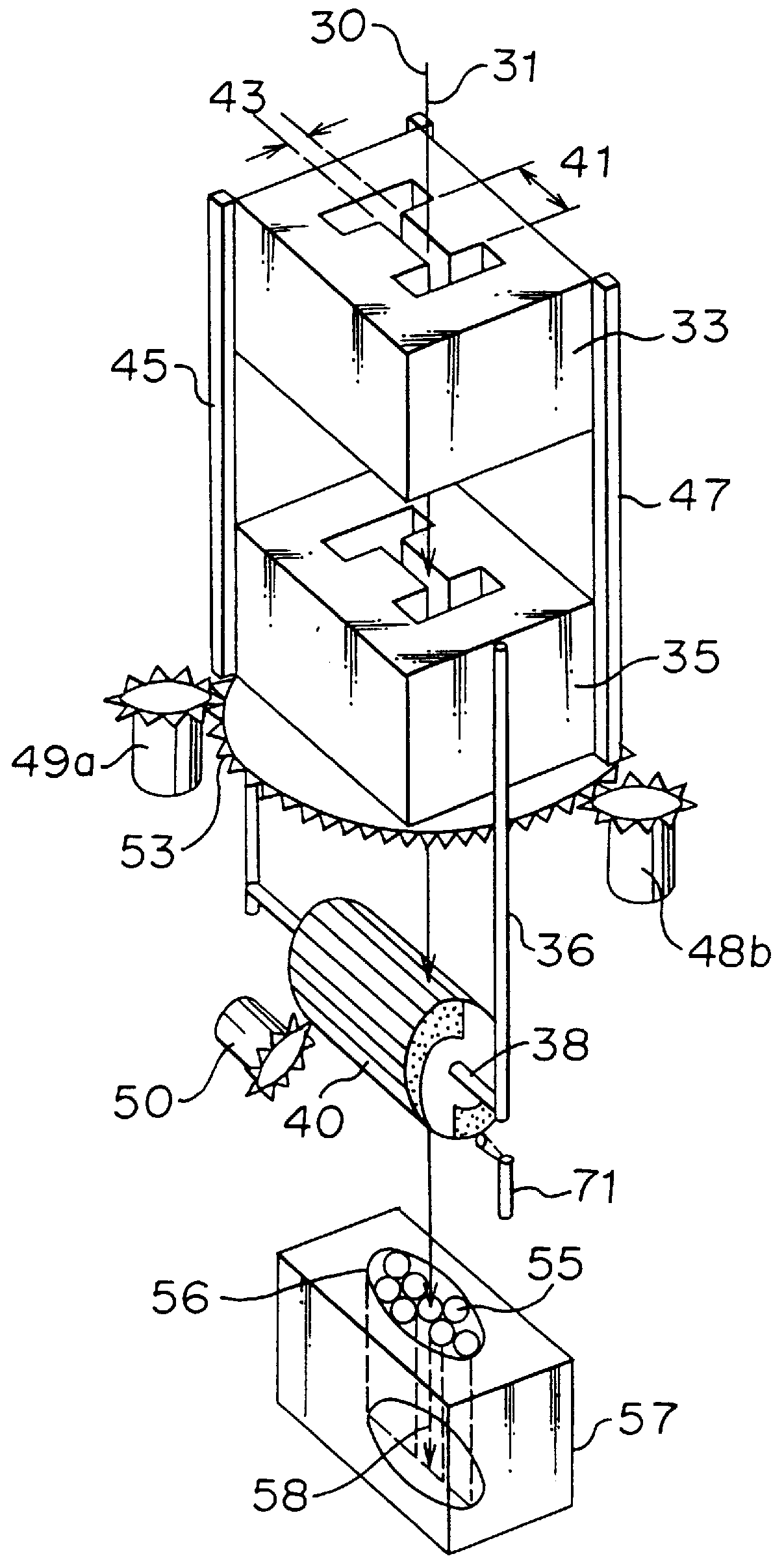
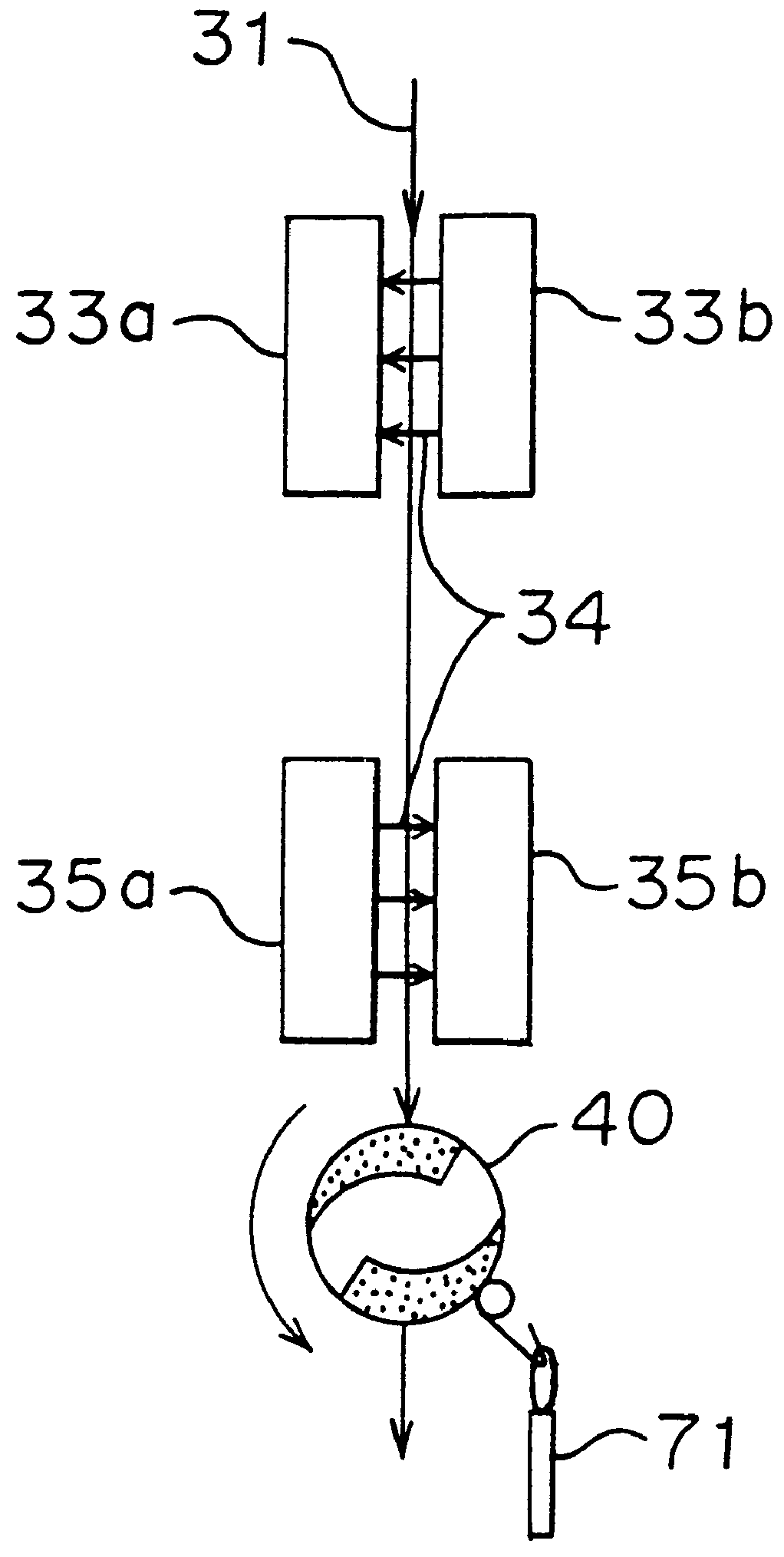
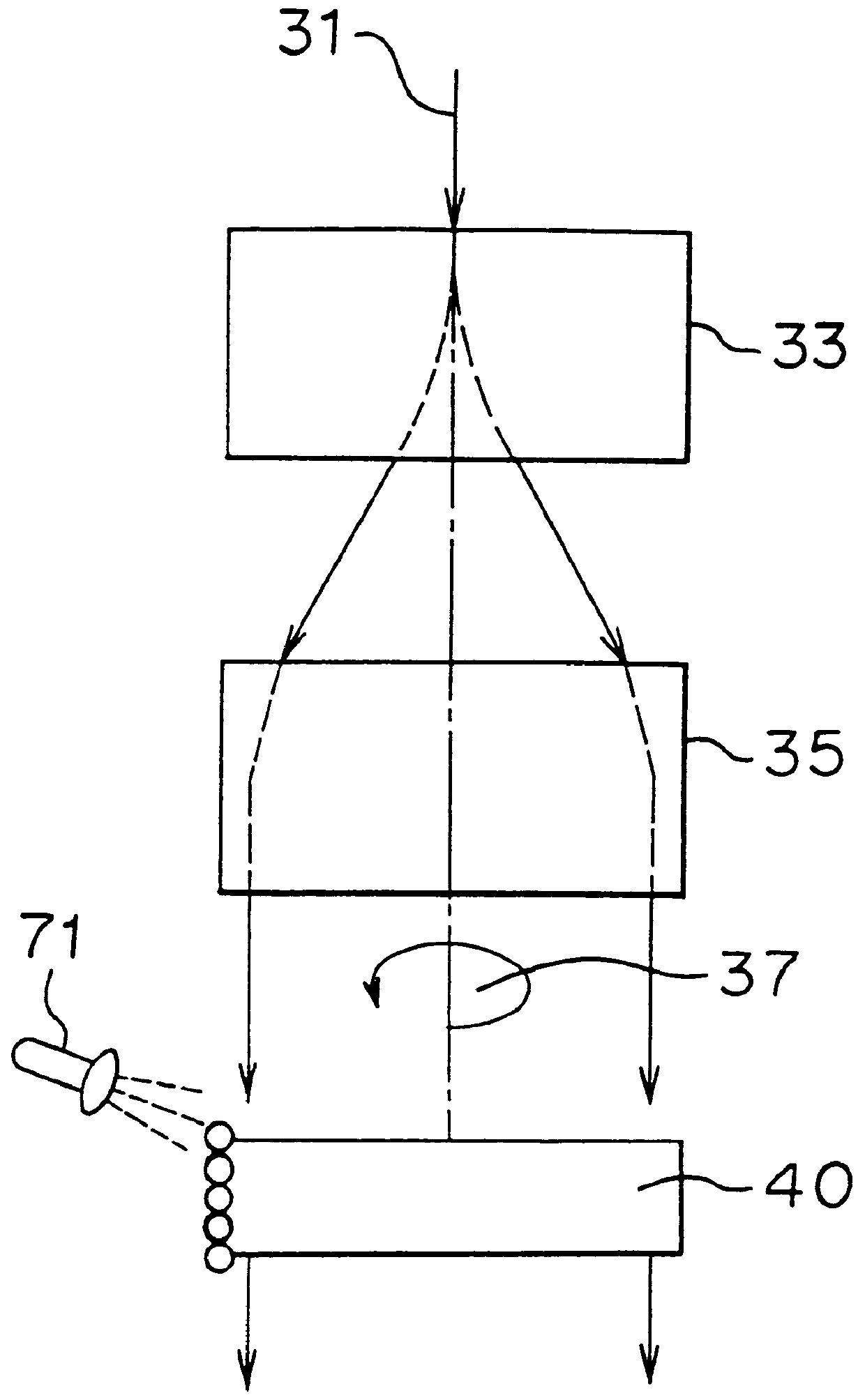
FIG. 5 is a block diagram showing a charged particle beam therapeutic apparatus according to Embodiment 3 of the present invention. In FIG. 5, reference numeral 31 designates a charged particle beam, numerals 33, 35 designate the same scanning electromagnets as used in Embodiment 1, numeral 40 designates the same energy modulator as used in Embodiment 1, numeral 37 designates the rotating axis of a one-piece body comprising the scanning electromagnets 33, 35 and the energy modulator 40, and numeral 55 designates a locus of a swept charged particle beam. The other reference numerals designate the same elements as those in FIGS. 1, 2, 3 and 7 as in well as FIG. 10 showing a conventional example.

The charged particle beam therapeutic apparatus according to Embodiment 3 of the present invention will be described with reference to FIGS. 5, 6, 7 and 9 wherein the same reference numerals designate the same or corresponding parts. In the charged particle beam therapeutic apparatus constructe...

embodiment 4

FIG. 8 is a flow chart showing a method of irradiating a charged particle beam according to Embodiment 4 of the present invention. Description will be made as to Embodiment 4 concerning the irradiation method with reference to FIG. 8 as well as FIG. 5 concerning Embodiment 3 and FIGS. 7 and 9 concerning Embodiment 1.

Step 1: in FIG. 7, a three-dimensional irradiation area is approximated to a group of cylindrical columns arranged in parallel to the charged particle beam incident axis 30, with predetermined spaces, wherein the coordinate Pi (73) of each cylindrical column in an XY plane (which is perpendicular to the direction of irradiation) is determined to be the position of irradiation; the length .DELTA.zi (75) of each cylindrical column is determined to be a scanning range in a beam propagating direction (a depth direction) at the beam irradiation position Pi (75), and the coordinate of the maximum depth of irradiation is to be zi (79) where i is an integer from 1 to N, and N is...


PUM


Abstract

A charged particle beam irradiation apparatus includes two electromagnets arranged in series along a direction of an incident axis of a charged particle beam, for deflecting the charged particle beam in opposite directions, an energy modulator including a cylindrical member having a length and a distribution of wall thickness in a circumferential direction, a first rotational drive for rotating the cylindrical member around a rotation axis, and a detector for detecting the angular position of the cylindrical member. The energy modulator is disposed at a downstream side of the scanning electromagnets so that the deflected charged particle beam passes through the rotation axis. The apparatus includes an energy degrader for limiting energy of the charged particle beam, and a second rotational drive for rotating the scanning electromagnets and the energy modulator together around the incident axis of the charged particle beam.

Description

1. Field of the InventionThe present invention relates to a charged particle beam irradiation apparatus and a method of irradiating an object with a charged particle beam. Further, the present invention relates to a therapeutic apparatus.2. Discussion of BackgroundFIG. 10 is a block diagram showing an example of a conventional therapeutic apparatus disclosed in "Medical Physics" 1995, vol. 22, p 37 by Pedroni et al. In the conventional therapeutic apparatus, a proton beam emitted from an accelerator 1 is carried by a transporting magnet 3, and is passed through an energy degrader 5 at the first stage, as an energy attenuating means in which a predetermined amount of energy is given to the proton beam. The proton beam is bent from the horizontal direction to an upward direction by a first deflection electromagnet 11, and is returned to the horizontal direction by a second deflection electromagnet 13. Further, the proton beam is converged by a converging electromagnet 15, and swept in...

Claims


Application Information

Patent Timeline
IPC IPC(8): G21K5/02G21K5/10A61N5/10G21K1/093G21K5/04
CPCA61N5/1043G21K5/02G21K5/10A61N2005/1087A61N2005/1095
Inventor PU, YUEHU
Owner MITSUBISHI ELECTRIC CORP
Why Eureka
Try Eureka