Charged particle irradiation system

a charge particle and irradiation system technology, applied in the field of charge particle irradiation system, can solve the problems of difficult instantaneous correction, inability to accurately make instantaneous correction, and the charge particle beam cannot reach the desired position at a target position further downstream so as to improve the irradiation position accuracy of the charged particle beam and reduce the possibility

Active Publication Date: 2010-11-23
HITACHI LTD
View PDF19 Cites 127 Cited by
  • Summary
  • Abstract
  • Description
  • Claims
  • Application Information

AI Technical Summary

Benefits of technology

[0009]An object of the present invention is to provide a charged particle irradiation system that is capable of improving the accuracy in irradiation position of a charged particle beam at a target position and is capable of decreasing the possibility that a normal tissue will be irradiated.
[0014]Because a beam position at a target position is calculated by the above-described configuration, it is possible to improve the accuracy in irradiation position of a charged particle beam at the target position and thereby to decrease the possibility that a normal tissue will be irradiated.
[0027]According to the present invention, it is possible to improve irradiation positional accuracy of a charged particle beam and thereby to decrease the possibility that a normal tissue will be irradiated with it.

Problems solved by technology

Therefore, in order to correctly correct the position and angle, it is necessary to perform the convergence a plurality of times. Thus, the problem with the above technology is that it is difficult to correctly make an instantaneous correction.
However, because both of the position and angle of the charged particle beam change, even if a charged particle beam position at the position of the charged-particle-beam-position monitor system is correct, there is a possibility that the charged particle beam will not reach the desired position at a target position further downstream of the charged particle beam in comparison with the charged-particle-beam-position monitor system.

Method used


Image

  • Charged particle irradiation system
  • Charged particle irradiation system
  • Charged particle irradiation system

Examples


Embodiment Construction

[0035]The configuration of a charged particle irradiation system and the operation thereof according to one embodiment of the present invention will be described with reference to FIGS. 1 through 7.

[0036]First of all, the overall configuration of the charged particle irradiation system according to this embodiment will be described with reference to FIG. 1.

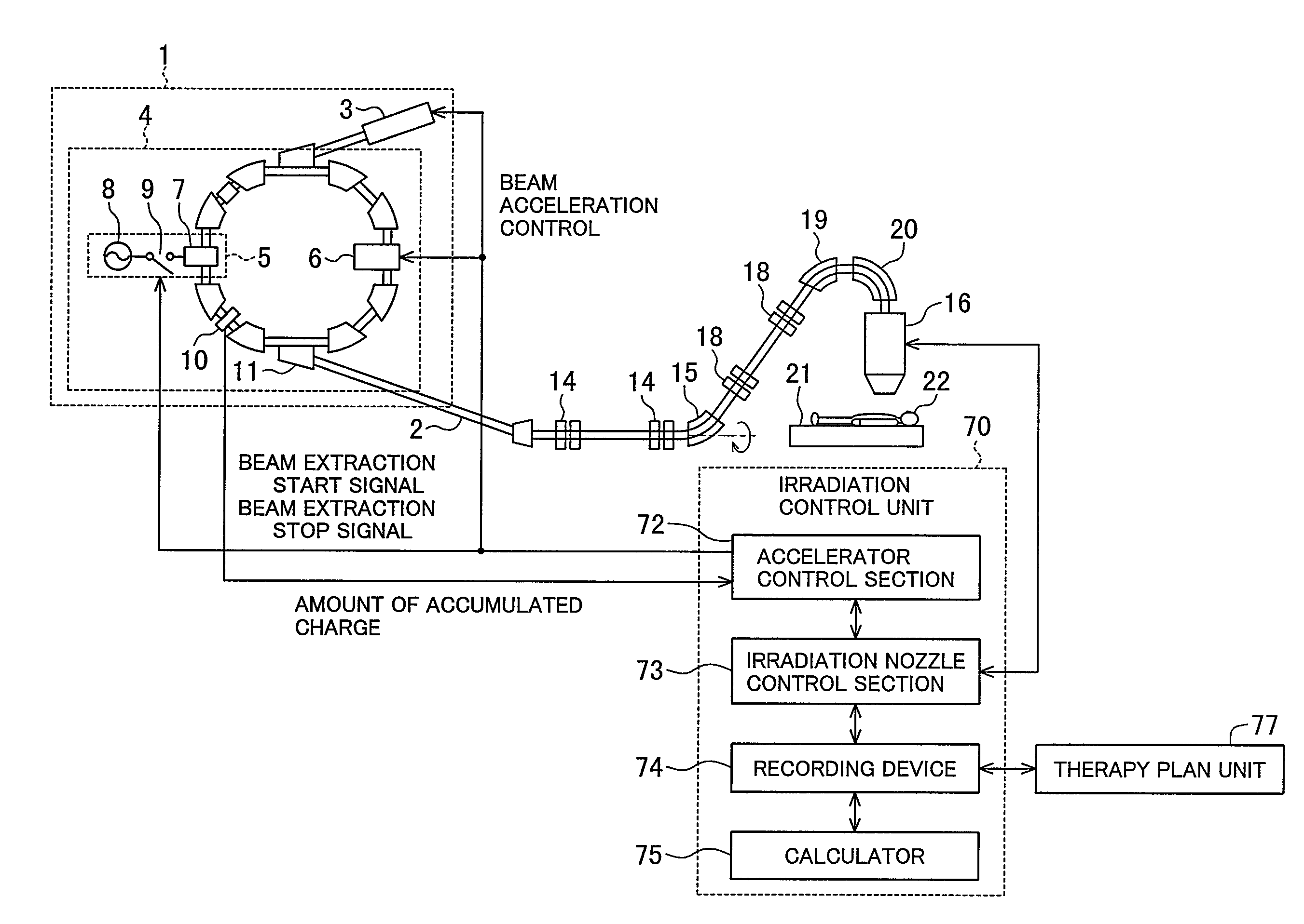
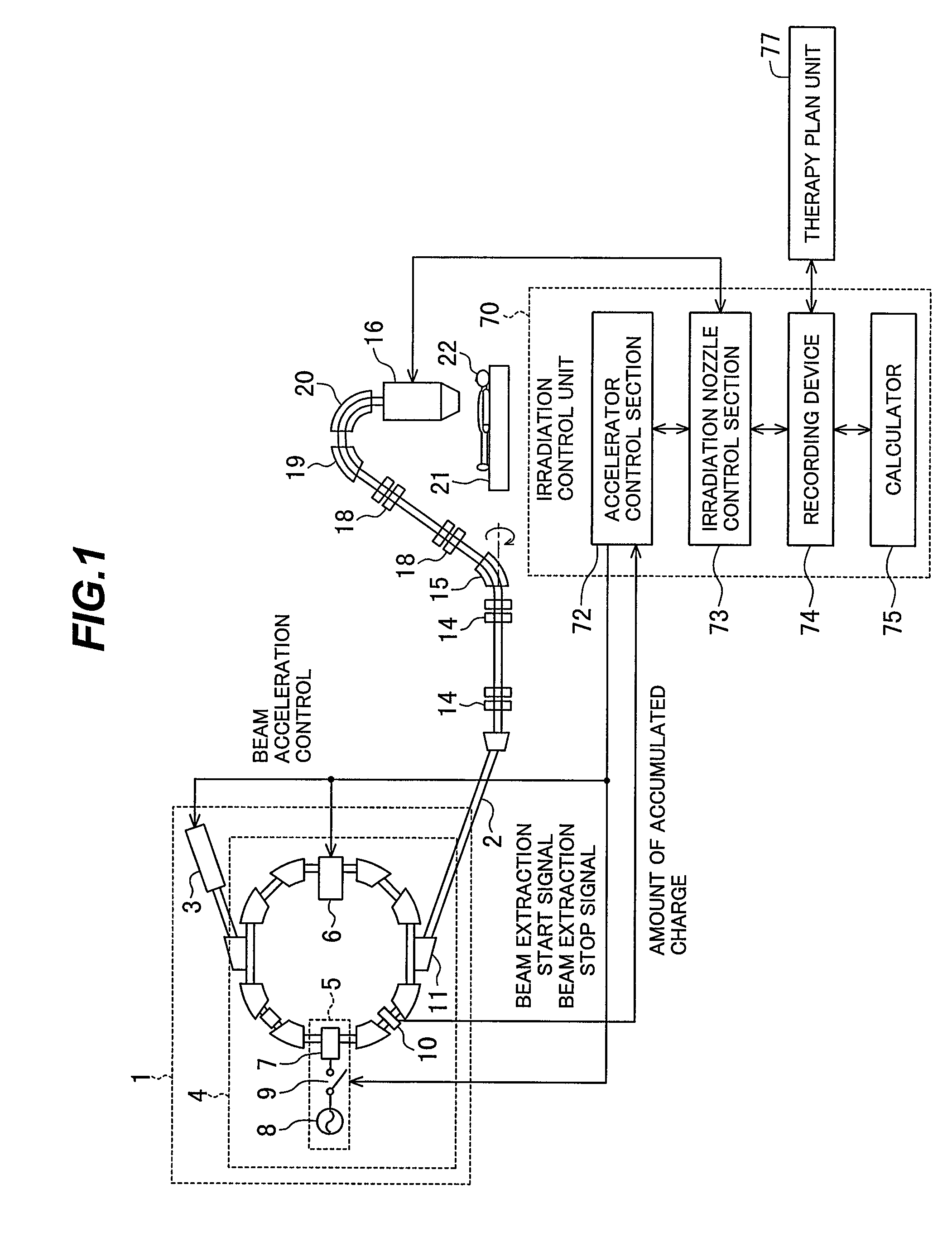
[0037]FIG. 1 is a system block diagram illustrating the overall configuration of a charged particle irradiation system according to one embodiment of the present invention.

[0038]The charged particle irradiation system according to this embodiment includes an ion beam generator 1, a beam transport line 2, an irradiation nozzle 16, and a control unit 70.

[0039]The ion beam generator 1 includes an ion source (not illustrated), a linear accelerator 3 (preaccelerator), and a synchrotron 4. The synchrotron 4 includes a radiofrequency acceleration system 5, an acceleration system 6, and an accelerated-charge amount monitor 10. The radiofr...


PUM


Abstract

A charged particle irradiation system that positions the beam at a target position to avoid irradiation of normal tissue includes an acceleration system 6 for extracting a charged particle beam, scanning magnets 24 and 25, and charged particle beam position monitors 26 and 27. On the basis of signals received from the charged particle beam position monitors 26 and 27, the control unit 70 calculates a beam position at a target position and then controls the scanning magnets 24 and 25 so that the charged particle beam is moved to a desired irradiation position at the target position. The control unit 70 corrects the value of an excitation current applied to each of the scanning magnets 24 and 25 on a specified cycle basis on the basis of information about the position and the angle of the charged particle beam.

Description

BACKGROUND OF THE INVENTION[0001]1. Field of the Invention[0002]The present invention relates to a charged particle irradiation system that is used to irradiate an affected part such as a tumor with a charged particle beam so as to treat the affected part and more particularly to a charged particle irradiation system that is suitable for the correction of a beam position.[0003]2. Description of the Related Art[0004]There is known a charged particle irradiation system for irradiating a patient such as a cancer patient with a charged particle beam such as a proton beam. This charged particle irradiation system includes an ion beam generator, a beam transport line, and a treatment room. A charged particle beam accelerated by the ion beam generator reaches an irradiation nozzle in the treatment room through the beam transport line. The charged particle beam is then scanned by a scanning magnet included in the irradiation nozzle so that an affected part of the patient is irradiated with ...

Claims


Application Information

Patent Timeline
Patent Type & Authority Patents(United States)
IPC IPC(8): A61N5/00G21K5/10H05H13/04
CPCA61N5/1048G21K5/04A61N2005/1087
Inventor FUJII, YUSUKEFUJIMAKI, HISATAKAHIRAMOTO, KAZUO
Owner HITACHI LTD
Why Eureka
Try Eureka