Inductively coupled plasma spectrometer for process diagnostics and control

a plasma spectrometer and inductive coupling technology, applied in the direction of optical radiation measurement, instruments, spectrometry/spectrophotometry/monochromators, etc., can solve the problems of complicated design and plasma ignition hardware, and achieve the effect of improving detector sensitivity

Inactive Publication Date: 2005-03-15
LIGHTWIND CORP
View PDF35 Cites 276 Cited by
  • Summary
  • Abstract
  • Description
  • Claims
  • Application Information

AI Technical Summary

Benefits of technology

Accordingly, the objects and advantages of the present invention are:(a) to provide a monitor, control or analysis tool that is less susceptible to control perturbations or errors in the primary process vessel,(b) to provide a remote plasma whose light intensity can be varied independently of the process reactor thereby giving an additional means to improve detector sensitivity(c) to provide a method where monitoring and analysis can be used to detect chemical abundances when low reaction rates, or no reaction exists to emit sufficient light.(d) to provide a simpler reactor design that does not require either double wall tubing, or a special inlet for swirling or mixing of carrier or sample gas(e) to provide an inductive source that is consistent with operating

Problems solved by technology

The designs also require complicated plasma ig

Method used


Image

  • Inductively coupled plasma spectrometer for process diagnostics and control
  • Inductively coupled plasma spectrometer for process diagnostics and control
  • Inductively coupled plasma spectrometer for process diagnostics and control

Examples


Embodiment Construction

—FIGS. 1, 2, 2A, and 2B—Preferred Embodiment

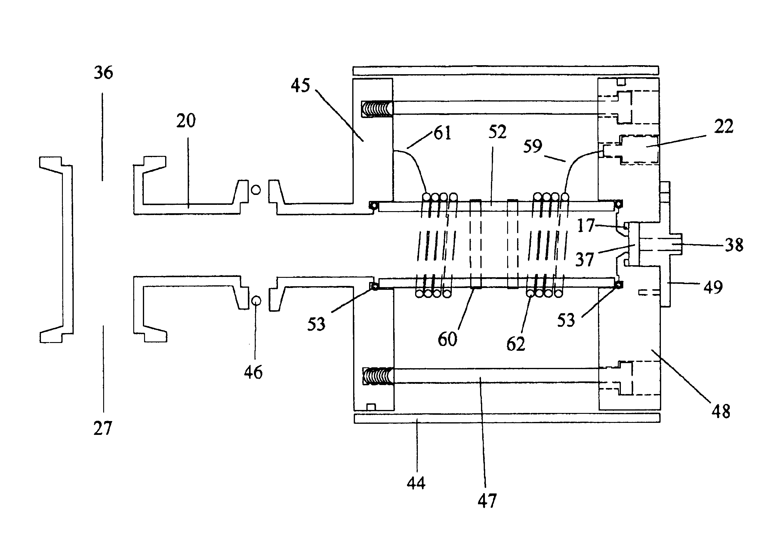
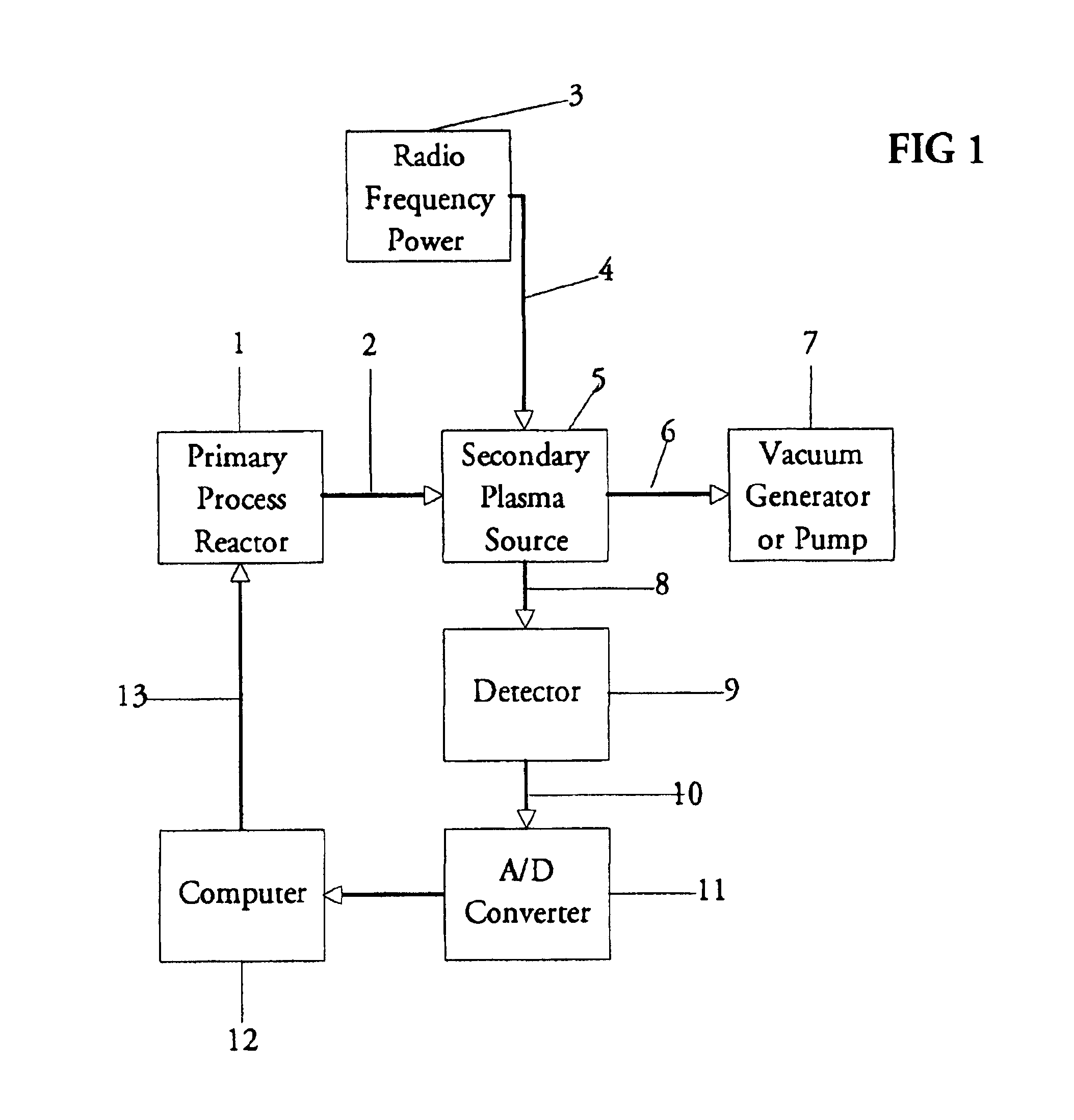
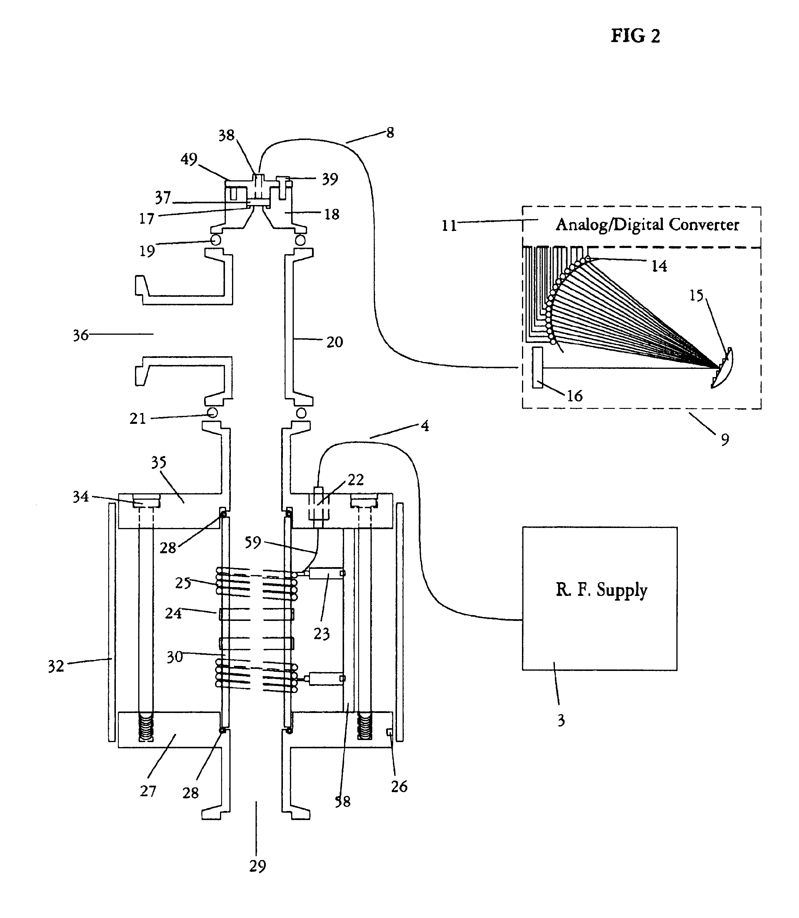
Referring now to the drawings, FIG. 1 shows a schematic overview of a secondary plasma source or generator 5 which has been inserted in a vacuum exhaust line 2 of a primary process reactor 1. The output of the plasma source 5 is connected to an exhaust line 6 which is connected to a vacuum pump or generator 7. A radio frequency power supply 3 provides sufficient energy at 13.56 megahertz through a cable4 to create a plasma in the source 5. A fiber optic cable 8 transmits emitted light from the plasma to a light detector 9. The light detector converts photonic energy into a packet of analog signals which are transmitted over a communication cable 10 to an analog / digital converter 11 and is then processed by a computer 12. The computer analyzes, monitors, and records time based data from the optical detector 9 and the appropriate information is sent over a communication cable 13 to the main processing reactor 1 where the information may be u...


PUM


Abstract

The present invention relates to an apparatus and method for forming a plasma in the exhaust line of a primary process reactor. The plasma is generated in an inductive source (5) to examine the chemical concentrations of the waste or exhaust gas in vacuum lines that are below atmospheric pressure. The optical radiation emitted by the plasma is analyzed by an optical spectrometer (9) and the resulting information is used to diagnose, monitor, or control operating states in the main vacuum vessel.

Description

BACKGROUND—FIELD OF INVENTIONThis invention relates to the production of gas plasmas to be used for spectroscopic examinations, more particularly it is directed toward use with effluent gases from a primary process reactor.BACKGROUND—DESCRIPTION OF PRIOR ARTThe reliability and reproducibility of many industrial processes are improved by the use of sensor based analytical equipment. In semiconductor manufacturing many of those processes occur under vacuum. When the processes occur light may be emitted as a byproduct of the reactions. That light is a composition of wavelengths which are characteristic and unique to the reactions occurring. Measurement and an analysis of that light is accomplished with the use of optical spectrometers. Spectral analysis provides a means to control or terminate the chemical processes; or in other instances it may be used to diagnose, evaluate and optimize the operation of the manufacturing equipment. While this approach is valuable there are severe limi...

Claims


Application Information

Patent Timeline
IPC IPC(8): G01J3/443G01N21/73H01J37/32H01L21/00
CPCG01J3/443G01N21/73H01L21/67253H01J37/32972H01L21/67069H01J37/32935
Inventor POWELL, GARY
Owner LIGHTWIND CORP
Why Eureka
Try Eureka