Substrate for growing carbon nanotubes, manufacturing method thereof, and manufacturing method of oriented carbon nanotubes

a technology of carbon nanotubes and substrates, which is applied in the direction of carbonsing rags, aligned nanotubes, plasma techniques, etc., can solve the problems of growing carbon nanotubes to be etched, and the average diameter of single-walled carbon nanotubes of less than 2 nm may not be elongated to a length of equal or more than 400 m

Inactive Publication Date: 2012-09-13
HONDA MOTOR CO LTD +1
View PDF0 Cites 4 Cited by
  • Summary
  • Abstract
  • Description
  • Claims
  • Application Information

AI Technical Summary

Benefits of technology

[0022]In the manufacturing method of oriented carbon nanotubes of the present invention, plasma is generated in a treatment chamber depressurized to a predetermined pressure under circulation of gas as a material for carbon nanotubes, and the substrate for gr

Problems solved by technology

However, there is such a problem in the method by the usage of plasma CVD that while carbon radicals are being generated in a plasma generation area, the substrate is attacked by ions generated as a by-product of the carbon radicals, which caused the growing carbon tubes to be etched.
Thereby, the method by the usage of plasma CVD is disadvantageous in growing long carbon nanotubes, and it is more disadvantageous in growing single-walled carbon nano

Method used


Image

  • Substrate for growing carbon nanotubes, manufacturing method thereof, and manufacturing method of oriented carbon nanotubes
  • Substrate for growing carbon nanotubes, manufacturing method thereof, and manufacturing method of oriented carbon nanotubes
  • Substrate for growing carbon nanotubes, manufacturing method thereof, and manufacturing method of oriented carbon nanotubes

Examples


first example

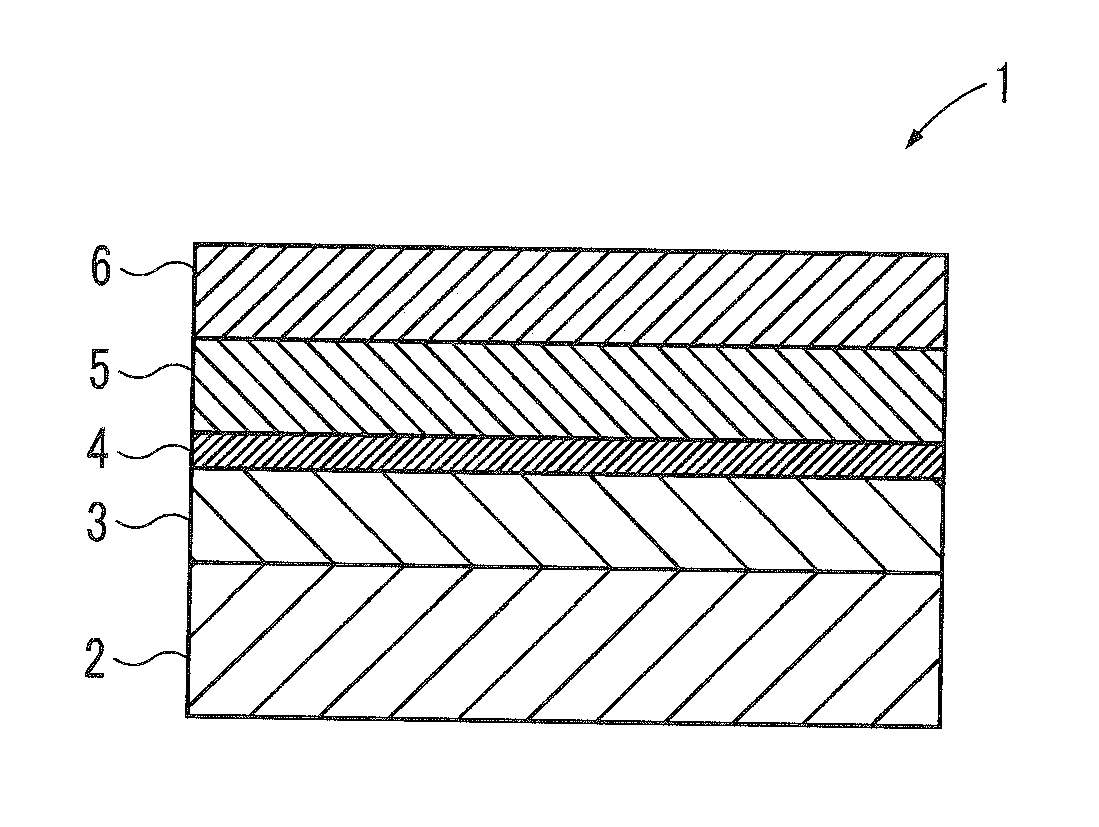
[0057]In the present example, Al was evaporated to a thickness of 5 nm according to the sputtering method on a base material 2 of silicone, and then by exposure to the atmosphere, a reaction prevention layer 3 of aluminum oxide was formed. Subsequently, Fe was evaporated to a thickness of 0.5 nm according to the sputtering method on the reaction prevention layer 3, and a catalyst material layer 4 of Fe was formed. Subsequently, Al was evaporated to a thickness of 1.0 nm according to the sputtering method on the catalyst material layer 4, and then by exposure to the atmosphere, a dispersion layer 5 of aluminum oxide was formed. Subsequently, Ti was evaporated to a thickness of 0.3 nm according to the sputtering method on the dispersion layer 5, and then by exposure to the atmosphere, a dispersion promotion layer 6 of titanium oxide was formed. As a result, the substrate for growing carbon nanotubes 1 equipped with the structure shown in FIG. 1 was obtained.

[0058]Subsequently, the sub...

example 2

[0061]In the present example, the substrate for growing carbon nanotubes 1 having the structure shown in FIG. 1 was obtained in the exact same manner as in Example 1, except that the thickness of the catalyst material layer 4 of Fe was 0.6 nm.

[0062]Next, the oriented carbon nanotubes were obtained in the exact same manner as in Example 1, except that the substrate for growing carbon nanotubes 1 obtained in the present example was used.

[0063]The G / D of the Raman spectrum of the oriented carbon nanotubes obtained in the present example is shown in FIG. 3.

example 3

[0064]In the present example, the substrate for growing carbon nanotubes 1 having the structure shown in FIG. 1 was obtained in the exact same manner as in Example 1, except that the thickness of the catalyst material layer 4 of Fe was 0.75 nm.

[0065]Next, the oriented carbon nanotubes were obtained in the exact same manner as in Example 1, except that the substrate for growing carbon nanotubes 1 obtained in the present example was used.

[0066]The G / D of the Raman spectrum of the oriented carbon nanotubes obtained in the present example is shown in FIG. 3.


PUM

PropertyMeasurementUnit
Thicknessaaaaaaaaaa
Diameteraaaaaaaaaa

Abstract

A substrate for growing carbon nanotubes capable of elongating single-walled carbon nanotubes of an average diameter of less than 2 nm is provided. The substrate for growing carbon nanotubes 1 is equipped with a reaction prevention layer 3 formed on a base material 2, a catalyst material layer 4 formed on the reaction prevention layer 3, a dispersion layer 5 formed on the catalyst material layer 4, and a dispersion promotion layer 6 formed on the dispersion layer 5.

Description

[0001]This application claims the foreign priority benefit under 35 U.S.C. §119 of Japanese Patent Application No. 2011-049601 filed on Mar. 7, 2011, the disclosure of which is incorporated herein by reference.BACKGROUND OF THE INVENTION[0002]1. Field of the Invention[0003]The present invention relates to a substrate for growing carbon nanotubes, a manufacturing method thereof, and a manufacturing method of oriented carbon nanotubes.[0004]2. Background Art[0005]Hitherto, there has been known an oriented carbon nanotube manufacturing method by the usage of a plasma CVD for manufacturing oriented carbon nanotubes oriented in a perpendicular direction to a substrate in the synthesis of multi-walled carbon nanotubes for an electric field emitter (for example, refer to Science, 282, 1105 (1998)).[0006]According to the method by the usage of plasma CVD, the improved field effect by a sheath formed by the plasma has been considered to contribute to the orientation of carbon nanotubes. Howe...

Claims


Application Information

Patent Timeline
IPC IPC(8): D01F9/12H05H1/02B82Y30/00B82Y40/00
CPCB82Y30/00B82Y40/00C01B31/0233D01F9/127Y10S977/843C01B2202/08C01P2002/82Y10S977/742D01F9/133C01B32/162
Inventor OHASHI, TOSHIYUKITOKUNE, TOSHIOOTA, MASAHIRONIKAWA, HIDEFUMIKAWARADA, HIROSHIOCHIAI, TAKUMI
Owner HONDA MOTOR CO LTD
Why Eureka
Try Eureka