
Device and method for testing reverse osmosis membranes

a reverse osmosis and membrane technology, applied in reverse osmosis, surface/boundary effect, instruments, etc., can solve the problems of requiring a great deal of effort, and achieve the effect of quick and efficien

Inactive Publication Date: 2012-09-20
KING FAHD UNIVERSITY OF PETROLEUM AND MINERALS
View PDF5 Cites 12 Cited by
  • Summary
  • Abstract
  • Description
  • Claims
  • Application Information

AI Technical Summary

Benefits of technology

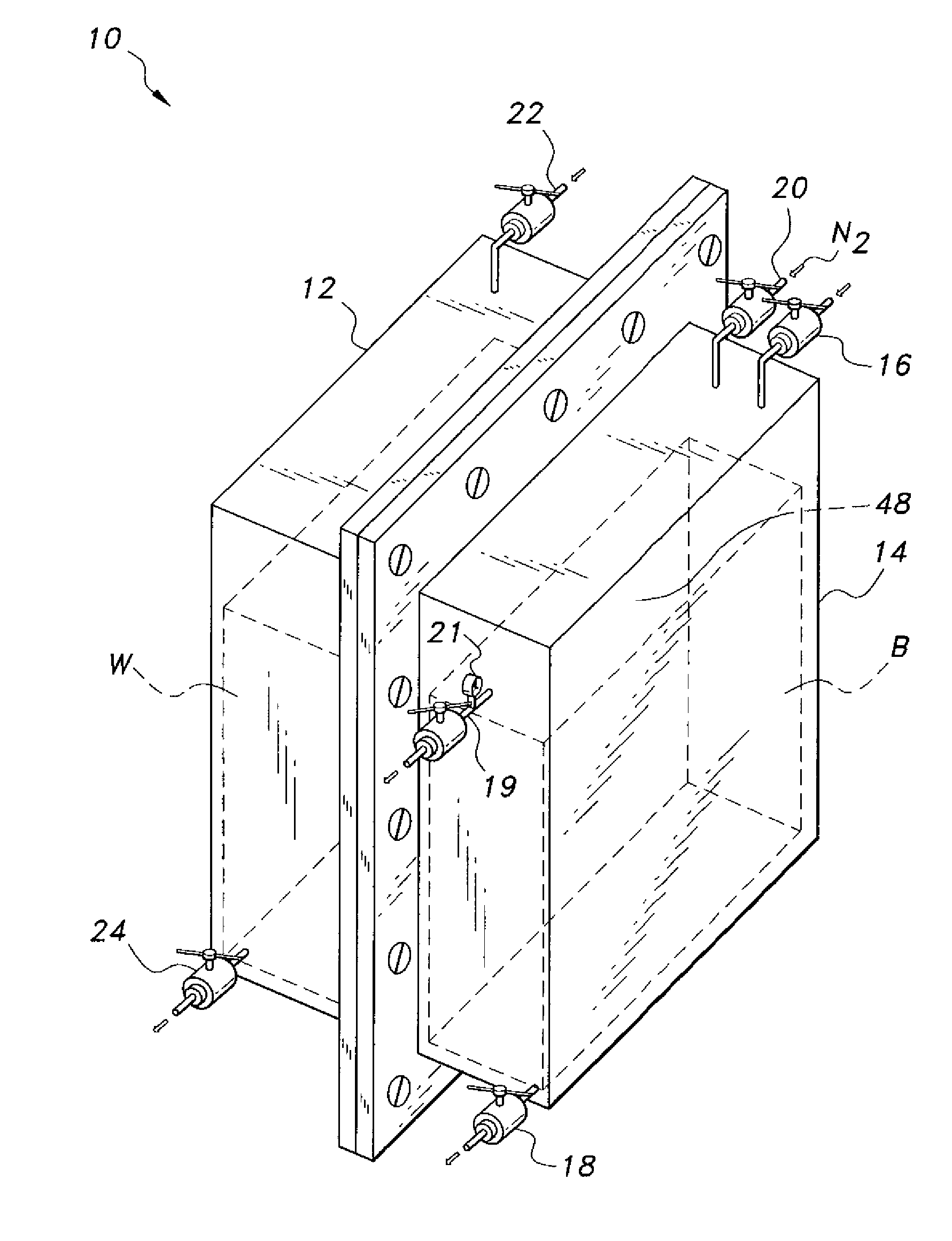
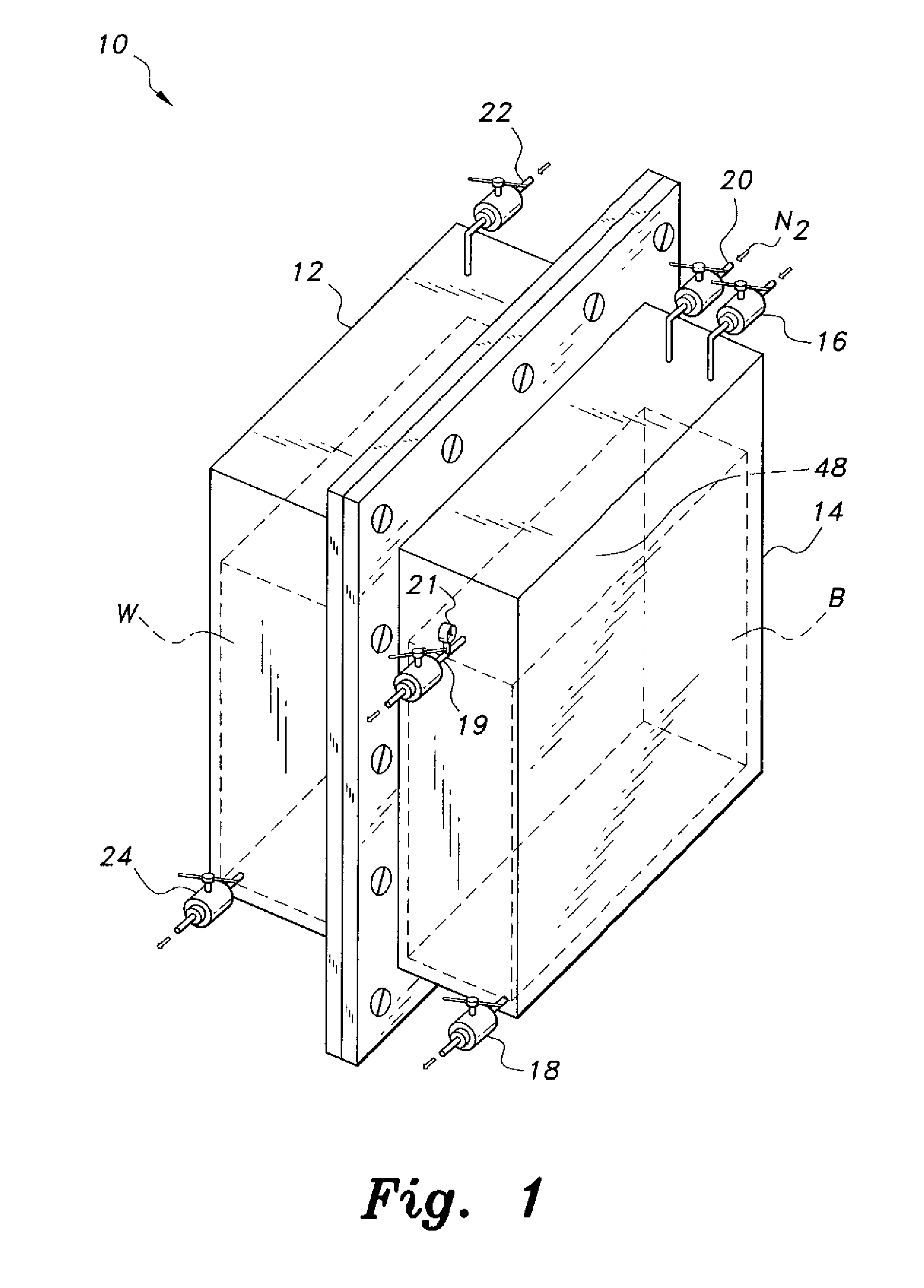
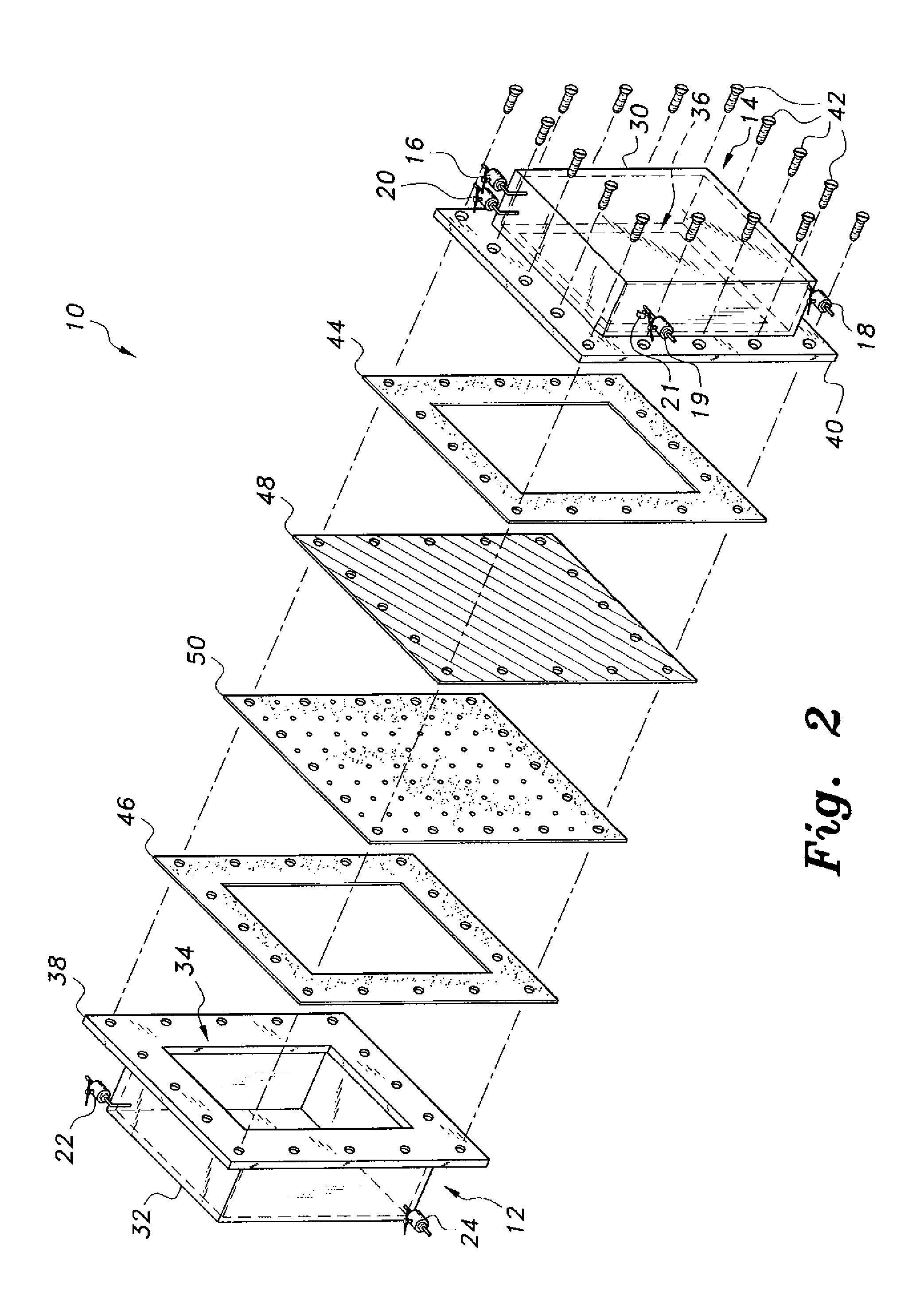
[0011]The device for testing reverse osmosis membranes provides for the quick and efficient testing of the transport properties of reverse osmosis membranes at a fixed pressure over a fixed period of time. The device includes a first chamber having a first housing, the first housing having at least one wall defining a first reservoir adapted for receiving a volume of de-ionized water. The first housing has an open proximal end and a first frame mounted thereto, bordering the open proximal end thereof. A second chamber is further provided having a second housing. The second housing similarly has at least one wall defining a second reservoir adapted for receiving a volume of brine. The second housing also has an open proximal end and a second frame mounted thereto, bordering the open proximal end thereof.
[0012]In use, a reverse osmosis membrane to be tested is releasably clamped between the first and second frames so that the open proximal end of the first housing is positioned against a first surface of the reverse osmosis membrane and the open proximal end of the second housing is positioned against an opposed second surface of the reverse osmosis membrane. Preferably, a porous membrane support is sandwiched between the first frame of the first housing and the reverse osmosis membrane to stabilize and support the reverse osmosis membrane during testing.

Problems solved by technology

Typical testing occurs dynamically in actual reverse osmosis processes, which are often performed in large-scale plants (particularly in desalination processes), thus requiring a great deal of effort.

Method used


Image

  • Device and method for testing reverse osmosis membranes
  • Device and method for testing reverse osmosis membranes
  • Device and method for testing reverse osmosis membranes

Examples


Embodiment Construction

[0020]Referring now to FIGS. 1 and 2, the device 10 for testing reverse osmosis membranes provides a static diffusion cell for the quick and efficient testing of the transport properties of reverse osmosis membranes at a fixed pressure over a fixed period of time. The device 10 includes a first chamber 12 having a first housing 32, the first housing 32 having at least one wall defining a first reservoir adapted for receiving a volume of de-ionized water W. Preferably, the first housing 32 is formed from an optically transparent material, allowing for direct optical measurements of volume and fluid concentration to be made through the at least one wall. As best shown in FIG. 2, the first housing 32 has an open proximal end 34 and has a first flange or frame 38 mounted thereto bordering the open proximal end 34.

[0021]Similarly, a second chamber 14 has a second housing 30. The second housing 30 similarly has at least one wall defining a second reservoir adapted for receiving a volume o...


PUM


Abstract

The device for testing reverse osmosis membranes provides for the quick and efficient testing of the transport properties of reverse osmosis membranes at a fixed pressure over a fixed period of time. The device includes a first chamber adapted for receiving a volume of de-ionized water and a second chamber adapted for receiving a volume of brine. In use, a reverse osmosis membrane to be tested is clamped between the first and second chambers and a pressurized inert gas, such as gaseous nitrogen, is injected into the second chamber at known pressure to initiate reverse osmosis transport. The transport is carried out at the known pressure for a fixed period of time, after which the concentration of brine volume of water in the first chamber is measured.

Description

BACKGROUND OF THE INVENTION[0001]1. Field of the Invention[0002]The present invention relates generally to laboratory testing of reverse osmosis apparatus, and particularly to a device and method for testing reverse osmosis membranes that provides a static diffusion cell for measurement of the efficiency of flat membranes used for reverse osmosis.[0003]2. Description of the Related Art[0004]Reverse osmosis (RO) is a method that removes many types of large molecules and ions from solutions by applying necessary pressure to the solution when it is on one side of a selectively permeable membrane to reverse the normal osmotic process. The result is that the solute is retained on the pressurized side of the membrane and the pure solvent is allowed to pass to the other side. In order to be “selective”, the membrane should not allow large molecules or ions through its pores, but should allow smaller components of the solution, such as the solvent, to pass freely.[0005]In the normal osmosis...

Claims


Application Information

Patent Timeline
IPC IPC(8): G01N13/04
CPCG01N13/04G01N15/0806B01D61/12B01D2313/26B01D65/102B01D2313/025B01D2313/18B01D63/087
Inventor RAHMAN, FAIZUR
Owner KING FAHD UNIVERSITY OF PETROLEUM AND MINERALS
Learn More