Solar light heat receiver, and solar light collecting and heat receiving system

a solar light and heat receiving technology, applied in the safety of solar heat collectors, light and heating equipment, machines/engines, etc., can solve the problems of large circumferential temperature difference, inefficient thermal energy generation, and temperature difference between light receiving surfaces b>503/, so as to improve the durability of heat receiving pipes, reduce temperature difference, and reduce the effect of temperature differen

Inactive Publication Date: 2012-09-20
MITSUBISHI HEAVY IND LTD
View PDF25 Cites 7 Cited by
  • Summary
  • Abstract
  • Description
  • Claims
  • Application Information

AI Technical Summary

Benefits of technology

[0027]In the sunlight collecting heat receiver of the invention, it is possible to improve the durability of the heat receiving pipe by reducing the temperature difference between the light receiving surface (the irradiation side) and the non-light receiving surface (the non-irradiation side) in the heat receiving pipe.
[0028]Further, in the sunlight collecting heat receiving system of the invention, since the sunlight collecting heat receiver of the invention is provided, it is possible to reduce the temperature difference between the light receiving surface (the irradiation side) and the non-light receiving surface (the non-irradiation side) and efficiently transfer the thermal energy from the sunlight to the heat medium.
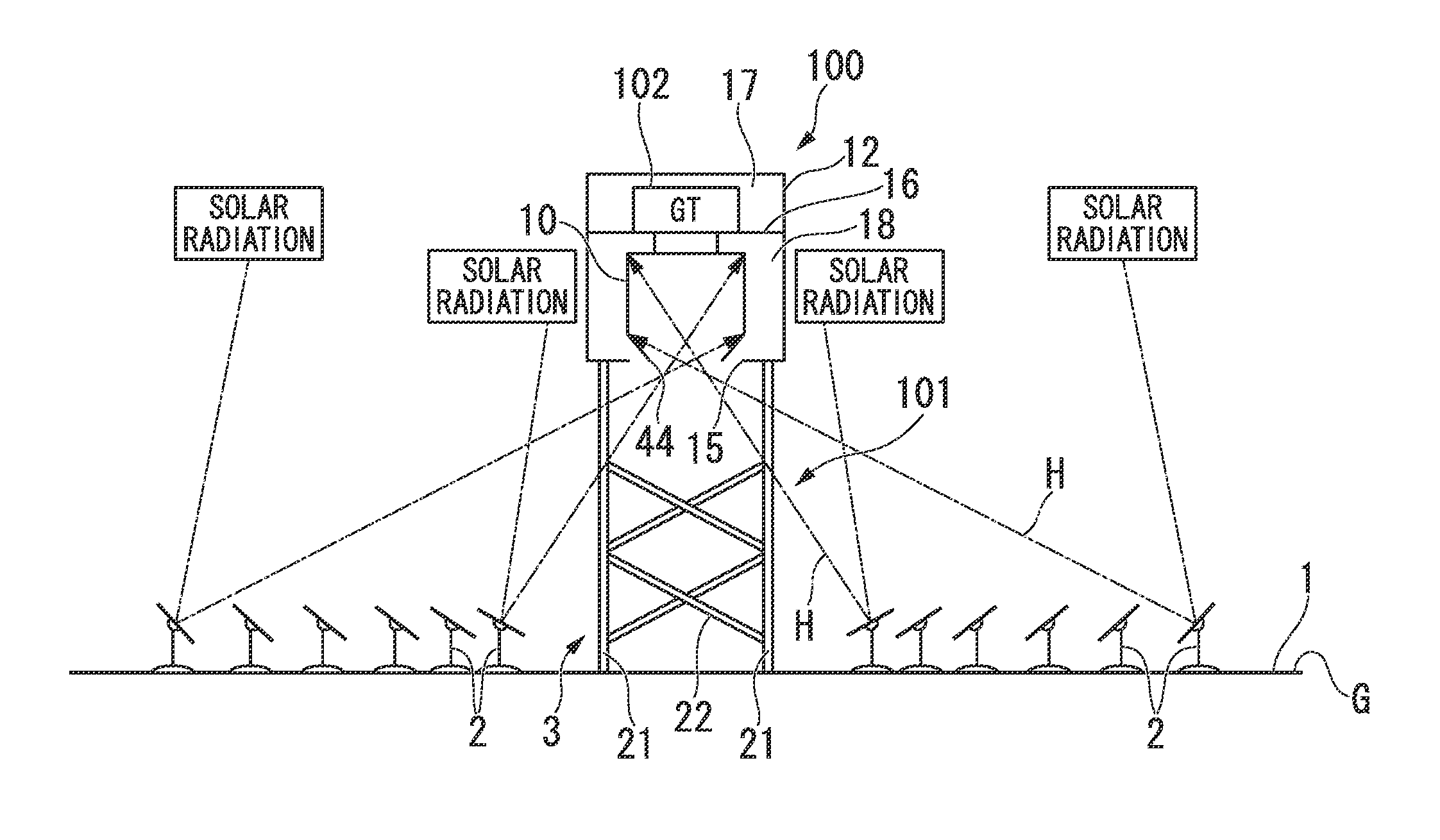
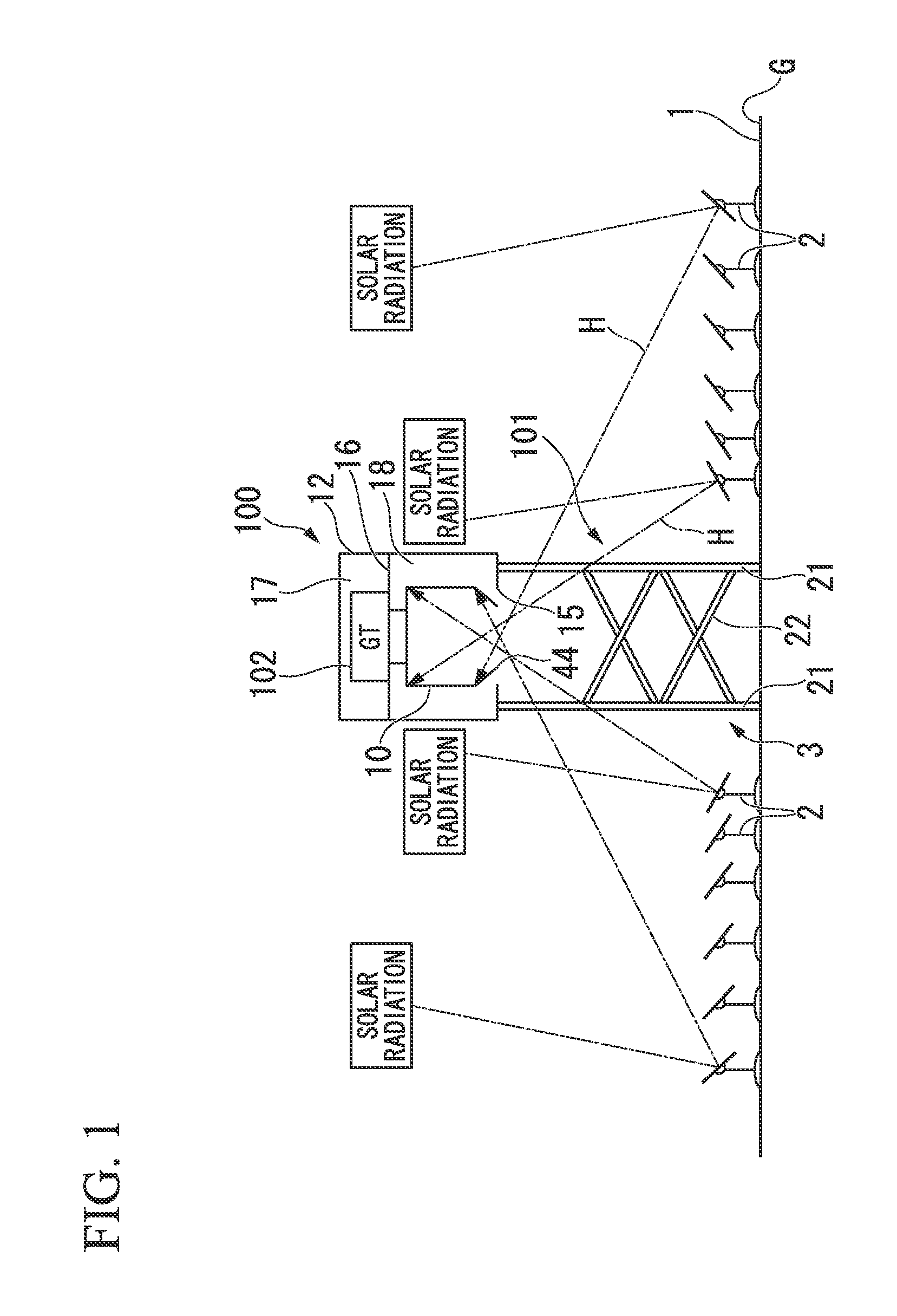
[0029]FIG. 1 is a diagram showing power generating equipment of an embodiment when seen from the side thereof.
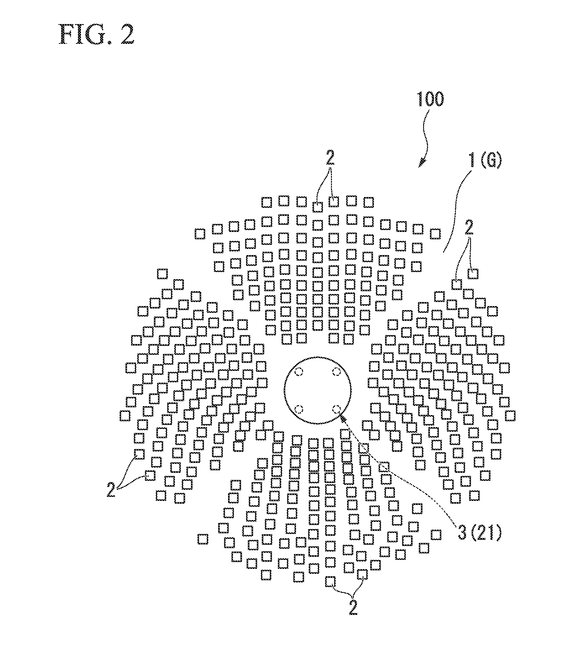
[0030]FIG. 2 is a diagram showing the power generating equipment of the embodiment when seen from the upside thereof.
[0031]FIG. 3A is a cross-sectional view showing the power generating equipment of the embodiment when seen from the upside thereof.
[0032]FIG. 3B is a cross-sectional view showing the power generating equipment of the embodiment when seen from the side thereof.

Problems solved by technology

However, in the above-described light collecting heat receiver 500, there is a problem in that a large temperature difference occurs in the circumferential direction (the outer peripheral surface) of each heat receiving pipe 503.
As a result, since thermal energy may not be efficiently obtained from the sunlight H′ in the non-light receiving surface 503b, there is a problem in that the temperature difference between the light receiving surface 503a and the non-light receiving surface 503b increases.

Method used


Image

  • Solar light heat receiver, and solar light collecting and heat receiving system
  • Solar light heat receiver, and solar light collecting and heat receiving system
  • Solar light heat receiver, and solar light collecting and heat receiving system

Examples


second embodiment

[0088]Next, a second embodiment of the invention will be described. FIG. 9 is a partially cutaway plan view showing a heat receiving unit of the embodiment. In the above-described embodiment, a configuration has been described in which the orifice plate 63 as the constraint means is disposed in the inlet of the non-light receiving side passageway 62 of each heat receiving pipe 51, but this embodiment is different from the above-described embodiment in that the constraint means is disposed in the low-temperature header 52. Furthermore, in the description below, the same reference signs will be given to the same components and the description thereof will be omitted.

[0089]As shown in FIG. 9, a heat receiving unit 142 of the embodiment has a configuration in which a plurality of partition walls 111 is provided at the same interval in the circumferential direction of the low-temperature header 152. Each partition wall 111 is disposed at one end of the outlet of each heat receiver supply...

third embodiment

[0095]Next, a third embodiment of the invention will be described. FIG. 10 is a cross-sectional view showing a heat receiving unit of the embodiment. Furthermore, in the description below, the same reference signs will be given to the same components and the description thereof will be omitted.

[0096]As shown in FIG. 10, inside the heat receiver body 41a heat receiving unit 242 of the embodiment includes a high-temperature header 253 which is disposed along the outer periphery of the ceiling plate portion 43, a low-temperature header 252 which is disposed at the inside of the high-temperature header 253 in the radial direction, and a plurality of heat receiving pipes 251 which makes the headers 252 and 253 communicate with each other. Furthermore, the low-temperature header 252 and the high-temperature header 253 are supported while being hung on the ceiling plate portion 43 by a plurality of hook members 245.

[0097]In each heat receiving pipe 251, one pipe is divided into a light rec...

fourth embodiment

[0101]Next, a fourth embodiment of the invention will be described. FIGS. 11A and 11B are cross-sectional views showing a heat receiving unit of the embodiment. In the embodiment, the arrangement direction of the heat receiving pipes 251 is reversed in the up-down direction compared to the third embodiment. Furthermore, in the description below, the same reference signs will be given to the same components and the description thereof will be omitted.

[0102]As shown in FIG. 11A, in the heat receiving unit 242 of the embodiment, the low-temperature header 252 and the high-temperature header 253 are disposed at the lower portion in the gravity direction inside the heat receiver body 41, and the plurality of heat receiving pipes 251 extends upward from the low-temperature header 252 and the high-temperature header 253.

[0103]Further, the ceiling plate portion 43 inside the heat receiver body 41 is provided with a plurality of hook members 345 which connects the ceiling plate portion 43 to...


PUM


Abstract

Disclosed is a solar light heat receiver having a heat receiving tube which allows a heat medium to flow through the inside thereof and which transmits the heat of irradiated solar light to the heat medium, the solar light heat receiver being provided with a partition member which divides the inside of the heat receiving tube into a first passage on the light receiving surface side to be irradiated with solar light, and a second passage on the non-light receiving surface side opposite to the first passage in the irradiation direction of solar light.

Description

TECHNICAL FIELD[0001]The present invention relates to a sunlight collecting heat receiver and a sunlight collecting heat receiving system which receive sunlight, convert the sunlight into high-temperature thermal energy, and transfer the thermal energy to a heat medium through a heat transfer.[0002]Priority is claimed on Japanese Patent Application No. 2009-291637, filed on Dec. 24, 2009, the content of which is incorporated herein by reference.BACKGROUND ART[0003]In recent years, as clean energy which does not affect the environment, an apparatus which uses thermal energy obtained by collecting sunlight is known. As such an apparatus, a sunlight collecting heat receiving system (hereinafter, referred to as a light collecting heat receiving system) has been developed which generates electric power by converting thermal energy into electric energy by collecting sunlight.[0004]In the above-described light collecting heat receiving system, a tower light collecting type is known as one ...

Claims


Application Information

Patent Timeline
Patent Type & Authority Applications(United States)
IPC IPC(8): F24J2/10F24J2/46F24J2/24F24S10/70F24S20/20F24S23/70
CPCY02E10/44Y02E10/46F03G6/00Y02E10/41F24J2/24F24J2/4636F24J2/07F24S10/70F24S20/20F24S40/80Y02E10/40
Inventor NAKATANI, HIROMI
Owner MITSUBISHI HEAVY IND LTD
Why Eureka
Try Eureka