Detection device

a detection device and humidity technology, applied in the direction of instruments, flow control, structural/machine measurement, etc., can solve the problems of inability to accurately detect the presence of humidity, the detection of humidity is difficult to achieve, and the prior art humidity detection devices are generally complex and expensive, so as to achieve reliable operation over time and increase the accuracy

Inactive Publication Date: 2012-09-20
ELTEK
View PDF9 Cites 29 Cited by
  • Summary
  • Abstract
  • Description
  • Claims
  • Application Information

AI Technical Summary

Benefits of technology

The technical effect of this patent is that it provides an improved detection device for systems used to treat or monitor exhaust gas emissions. This device has better reliability and accuracy over longer periods of use compared to previous versions.

Problems solved by technology

The technical problem addressed in this patent is the lack of reliable and cost-effective methods for accurately detecting the humidity of exhaust gases in internal combustion engines. This can affect the accuracy of measures made based on the presence of certain substances in the exhaust gas, which can impact their performance and efficiency.

Method used


Image

  • Detection device
  • Detection device
  • Detection device

Examples


Embodiment Construction

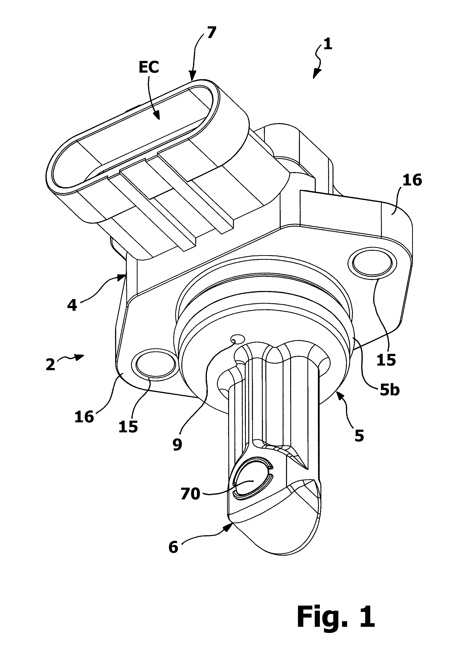
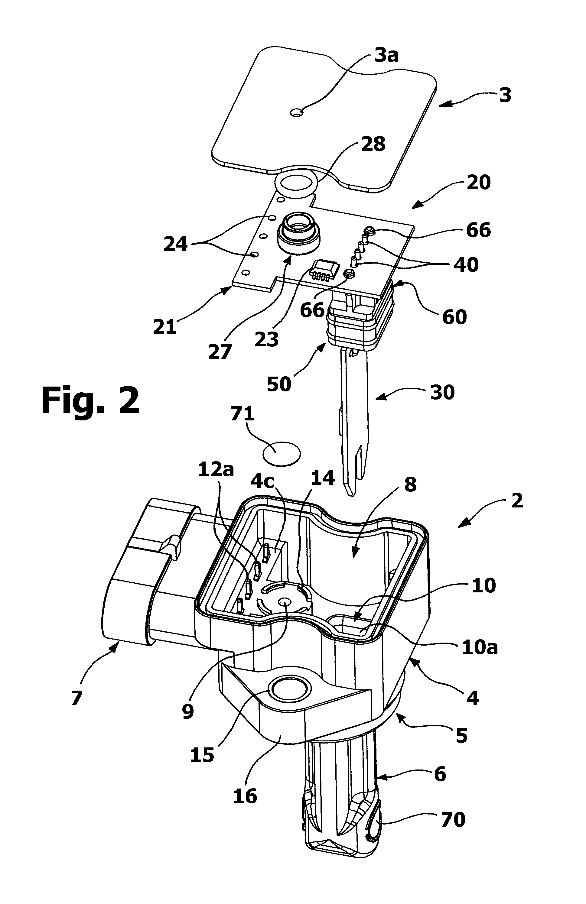
[0041]With particular reference to FIGS. 1-5, a detection device according to the invention is indicated in its entirety with 1, in whose structure two main parts can be identified, whose bodies are indicated with 2 and 3: the body 2 essentially meets housing / support, fluidic connection and electrical connection functions, while the body 3 essentially meets the cover functions. The bodies 2 and 3 are mutually coupled, preferably sealingly, to obtain a casing for internal components of the device 1, described hereinafter, as observable for example in FIGS. 6-8. In an embodiment, the bodies 2 and 3 are formed using a relatively rigid material, such as a thermoplastic material, and are preferably made at least in part through a moulding process.

[0042]In an embodiment, the body 2 has an upper portion 4, an intermediate portion 5, a lower portion 6 and a lateral portion 7 essentially tubular. As observable particularly in FIGS. 2, 9 and 11, a first cavity or chamber 8, beneath which the ...


PUM


Abstract

A detection device for internal combustion engines exhaust gases post-treatment systems has a casing (2, 3) housing a circuit arrangement (21, 31) including humidity sensor means (32), for measuring the humidity of the gas. The circuit arrangement further comprises temperature sensor means (33) and pressure sensor means (22), for detecting a gas temperature value and a gas pressure value, respectively. The gas temperature value can be used for compensating the humidity value obtained through the humidity sensor means (32) and the pressure value can be used for deducing the clogging degree of a filter of the post-treatment system. Preferably the pressure sensor means (22) are housed in a first chamber (8) of the casing (2-3) while the humidity sensor means (32) and the temperature sensor means (33) are housed in a second chamber (10b) of the casing (2, 3).

Description


Claims


Application Information

Patent Timeline
Owner ELTEK
Why Eureka
Try Eureka