Control device for power device

Active Publication Date: 2012-09-20
HONDA MOTOR CO LTD
View PDF3 Cites 36 Cited by
  • Summary
  • Abstract
  • Description
  • Claims
  • Application Information

AI Technical Summary

Benefits of technology

[0029]Therefore, by setting the cut-off frequency or the gain appropriately, the first filtering element and the second filtering element may determine the operation target so as to be capable of effectively suppressing the driving force transmitted from the actuator to the driven element from vibrating which is caused by the elastic characteristics of both of the fir

Problems solved by technology

As such, in such a power device, vibration caused by a resonance phenomenon and the like is easily generated, and consequently, vibration of the driving force transmitted to the driven element from the actuator is easily generated.
Therefore, the

Method used


Image

  • Control device for power device
  • Control device for power device
  • Control device for power device

Examples


Embodiment Construction

[0074]An embodiment of the present invention will be explained with reference to FIG. 1 through FIG. 4.

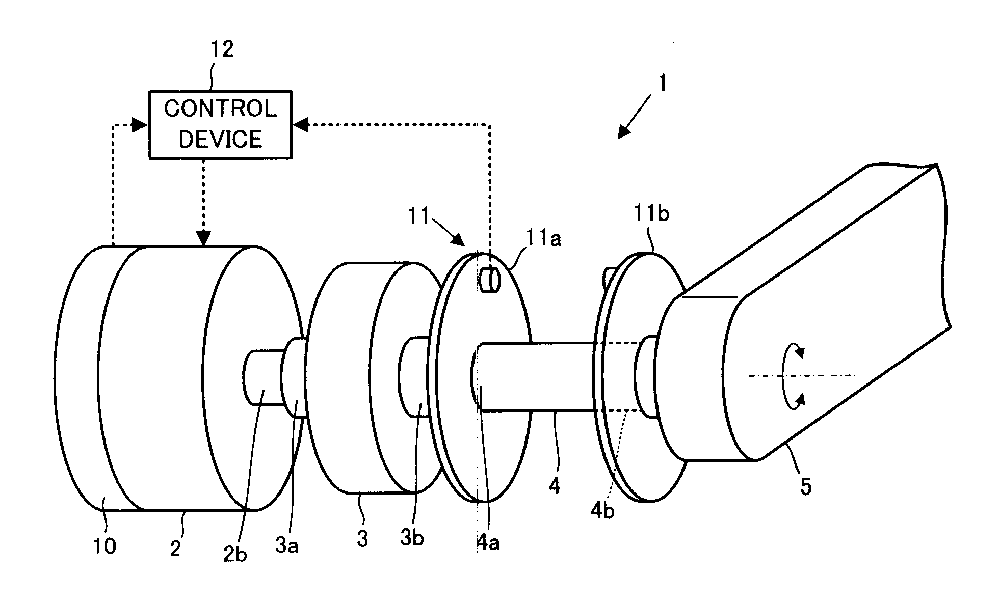
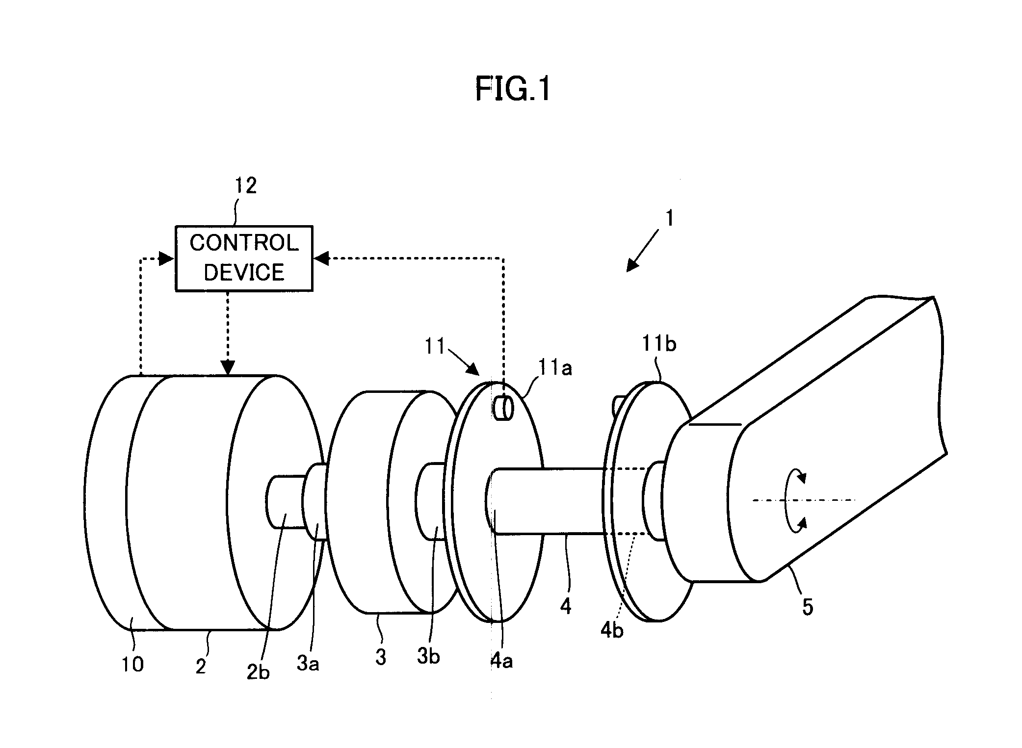
[0075]With reference to FIG. 1, a power device 1 of the present embodiment is a device which rotary drives a driven rotary member 5 as a driven element by an electric motor 2, and is equipped with a speed reducer 3 and a torsion bar 4 which is a spring member in a power transmission system between the electric motor 2 and the driven rotary member 5.

[0076]In the present embodiment, the electric motor 2, the speed reducer 3, and the torsion bar 4 respectively corresponds to an actuator, a first power transmission element, and a second power transmission element of the present invention. An example of the driven rotary member 5 includes a constituent element of a joint of a robot (a link member capable of freely rotating about a joint axis).

[0077]An output shaft 2b as a power output unit of the electric motor 2 is connected with an input shaft (an input unit) 3a of the speed reducer 3...


PUM


Abstract

In a power device 1 having a speed reducer 3 and a spring member 4 having elastic characteristics to a power transmission system between an actuator 2 and a driven element 5, an operation target of the actuator 2 is determined according to a linear coupling value of values that are obtained by passing through low-pass filters, a deviation Δω12 between an estimated value ω1_e of a displacement velocity of an input unit 4a of the spring member 4 and an estimated value ω2_e of a displacement velocity of the driven element 5, and a deviation Δθdef between a measured value θdef_s of a deviation difference between the input unit 4a of the spring member 4 and the driven element 5, and a target value θdef_cmd of the displacement difference corresponding to a target driving force τref of the driven element 5.

Description

BACKGROUND OF THE INVENTION[0001]1. Field of the Invention[0002]The present invention relates to a device which controls a driving force to be imparted to a driven element, such as a link of a robot, from an actuator.[0003]2. Related Background Art[0004]In a power device for driving a joint mechanism of a robot, in order to provide flexibility to the joint mechanism, there is known a type in which a spring member is provided between a power output unit of the actuator and a driven element of the joint mechanism.[0005]For example, in Patent Document 1, there is disclosed a power device which is configured so as to transmit a rotational driving force of a motor via a pulley and a speed reducer, and a damping element-elastic element system comprising a damper and a spring, in this order. Thereafter, in the technique shown in Patent Document 1, a target torque of the motor is determined on the basis of a target link angle, a measured value of the link angle, and a measured value of a ro...

Claims


Application Information

Patent Timeline
IPC IPC(8): B25J13/00
CPCG05B2219/41251B25J9/1641B25J9/0015B25J9/1633B25J13/088
Inventor ORITA, ATSUOTAKEMURA, YOSHINARI
Owner HONDA MOTOR CO LTD
Why Eureka
Try Eureka