
Manufacturing method for toothed part and manufacturing device for toothed part

a manufacturing device and technology for toothed parts, applied in manufacturing tools, forging/hammering/pressing machines, transportation and packaging, etc., can solve the problems of reducing the thickness of the workpiece, and complicating the structure of the shaping die. , to achieve the effect of simple structur

Inactive Publication Date: 2012-09-27
AISIN AW CO LTD
View PDF7 Cites 11 Cited by
  • Summary
  • Abstract
  • Description
  • Claims
  • Application Information

AI Technical Summary

Benefits of technology

"The present invention provides a manufacturing method and device for a toothed part that allows for the use of simple shaping dies and a simple process for manufacturing the toothed part in a desired shape. The method includes a half drawing process and a tooth shaping process, which prevents thinning of the material and allows for the manufacture of a toothed part with a sufficient thickness. The manufacturing device includes a toothed punch, a drawing die, and a toothed die, which can be easily inserted and moved with respect to each other to perform the necessary shaping. Overall, the invention simplifies the manufacturing process for toothed parts and allows for the use of more complex shaping dies."

Problems solved by technology

In the method and device for manufacturing a toothed part disclosed in Japanese Patent Application Publication No. 2006-116593, however, the round punch is disposed via the compression punch sleeve on the outer side of the toothed punch, which may complicate the structure of shaping dies.
Therefore, a tensile stress may be caused at the point of the workpiece contacted by the toothed portion, which may thin the workpiece (reduce the thickness of the workpiece).
If the workpiece is thinned in this way, a toothed part in a desired shape with a sufficient thickness may not be manufactured.

Method used


Image

  • Manufacturing method for toothed part and manufacturing device for toothed part
  • Manufacturing method for toothed part and manufacturing device for toothed part
  • Manufacturing method for toothed part and manufacturing device for toothed part

Examples


Embodiment Construction

[0042]An embodiment of the present invention will be described in detail below with reference to the accompanying drawings.

[0043][Configuration of Manufacturing Device]

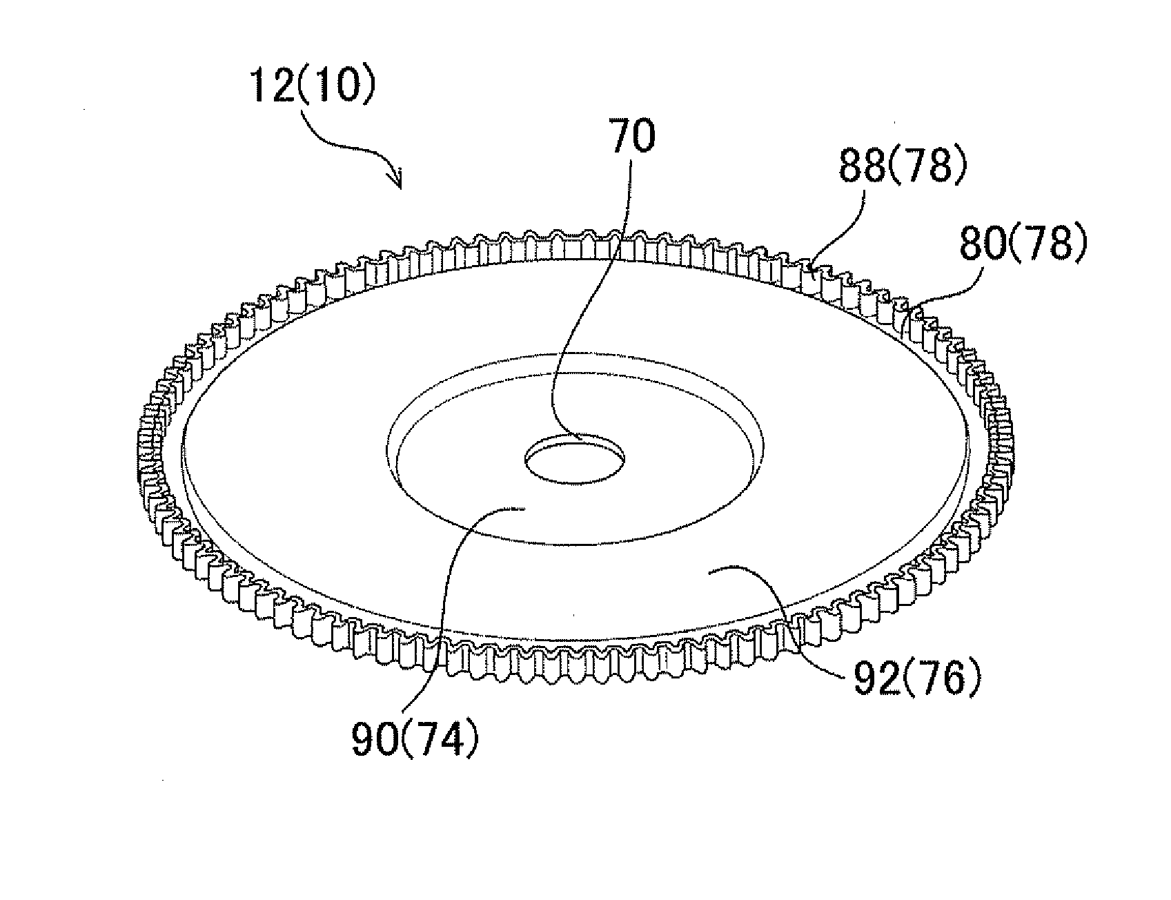
[0044]First, the configuration of a manufacturing device 1 for a toothed part according to the embodiment will be described. The manufacturing device 1 for a toothed part shapes a workpiece 10 which is a flat disk-shaped material to manufacture a toothed part 12 (see FIG. 17).

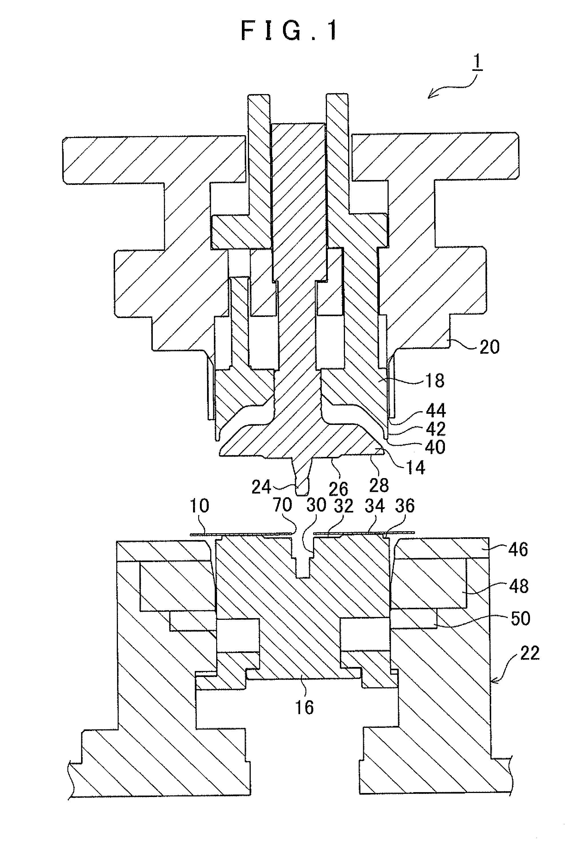
[0045]FIG. 1 shows the overall configuration of the manufacturing device 1 for a toothed part. FIG. 1 shows a state in a workpiece placement process to be discussed later. As shown in FIG. 1, the manufacturing device 1 for a toothed part includes a first restraint punch 14, a second restraint punch 16, a toothed punch 18, a compression punch 20, and a die portion 22.

[0046]The first restraint punch 14 is disposed at a position at which it faces the second restraint punch 16 (at a position on the upper side of FIG. 1). A surface of the first restra...


PUM

PropertyMeasurementUnit
diameteraaaaaaaaaa
tensile stressaaaaaaaaaa
thicknessaaaaaaaaaa

Abstract

A manufacturing method for a toothed part including a bottom surface portion and a side wall portion provided to extend upright from an outer peripheral end portion of the bottom surface portion, the side wall portion being fanned with teeth. The manufacturing method includes a half drawing process of performing draw shaping on a material having a disk shape to form the bottom surface portion and the side wall portion, an inside diameter of which becomes larger in a direction away from the bottom surface portion; and a tooth shaping process of forming the teeth in the side wall portion.

Description

INCORPORATION BY REFERENCE[0001]The disclosure of Japanese Patent Application No. 2011-066334 filed on Mar. 24, 2011 including the specification, drawings and abstract is incorporated herein by reference in its entirety.BACKGROUND OF THE INVENTION[0002]The present invention relates to a manufacturing method for a toothed part including a bottom surface portion and a side wall portion in an annular shape provided to extend upright in the axial direction from an outer peripheral end portion of the bottom surface portion and formed with teeth, and to a manufacturing device for the toothed part.DESCRIPTION OF THE RELATED ART[0003]Japanese Patent Application Publication No. 2006-116593 discloses a method and a device for manufacturing a toothed part (cup-shaped part) including a bottom surface portion and a side wall portion in an annular shape from a workpiece which is a flat disk-shaped material. Japanese Patent Application Publication No. 2006-116593 discloses that draw shaping and to...

Claims


Application Information

Patent Timeline
Patent Type & Authority Applications(United States)
IPC IPC(8): B21K1/30B21J13/02
CPCB21D53/28B21K1/30Y10T29/49474Y10T29/49472Y10T29/49462B23P15/14B21D22/30
Inventor IWATA, DAISUKEHORI, TOMOYUKIYOKOYAMA, NAOKISHIBATA, HIROSHIMAKI, MASAYUKI
Owner AISIN AW CO LTD
Learn More