Vehicle bearing device

a technology for bearings and vehicles, applied in the direction of bearing units, rigid support of bearing units, instruments, etc., can solve the problem of reducing the efficiency of manufacturing hub spindles, and achieve the effect of convenient formation

Inactive Publication Date: 2012-09-27
JTEKT CORP
View PDF3 Cites 4 Cited by
  • Summary
  • Abstract
  • Description
  • Claims
  • Application Information

AI Technical Summary

Benefits of technology

[0009]The invention provides a vehicle bearing device in which a plurality of grinding undercut portions is easily formed in a hub spindle through turning.

Problems solved by technology

Therefore, there is a problem that the turning process for the grinding undercut portions 119a to 119c is complex, which reduces the efficiency of manufacturing the hub spindle 101.

Method used


Image

  • Vehicle bearing device
  • Vehicle bearing device
  • Vehicle bearing device

Examples


Embodiment Construction

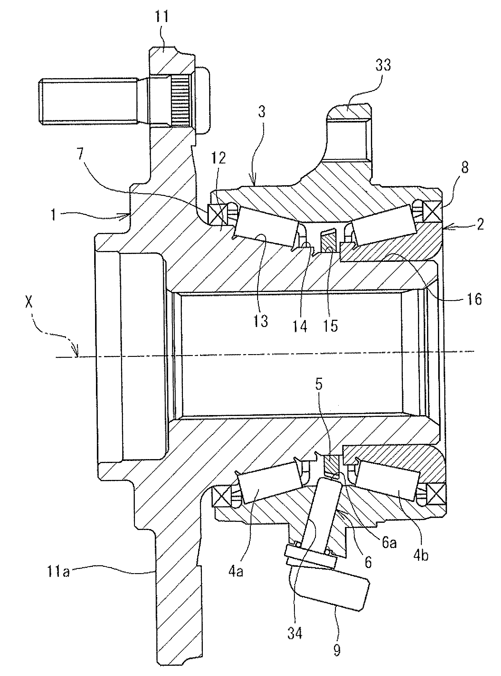
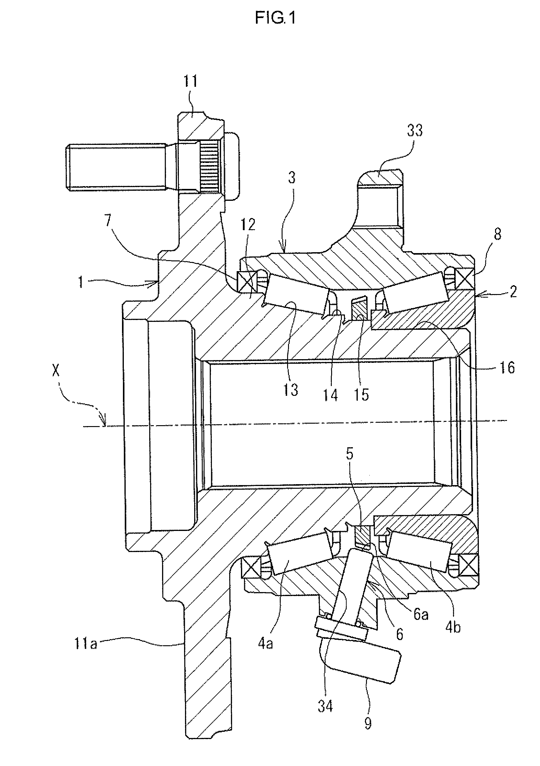
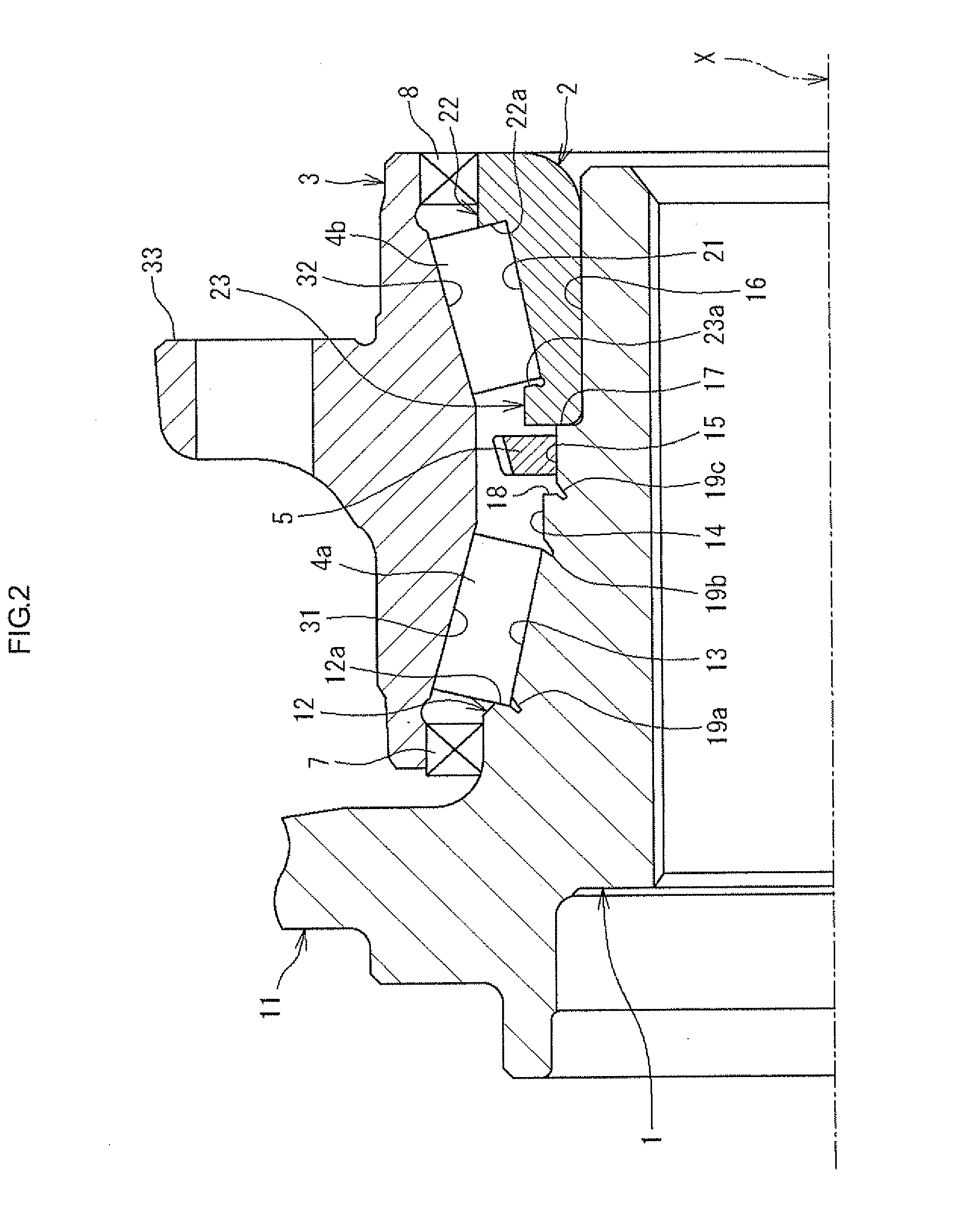
[0016]Hereinafter, an embodiment of the invention will be described in detail with reference to the accompanying drawings. FIG. 1 is a longitudinal sectional view of a vehicle bearing device according to the embodiment of the invention. FIG. 2 is an enlarged longitudinal sectional view of main portions in FIG. 1. In FIG. 1, the vehicle bearing device is used to support a wheel of a vehicle, such as an automobile, and includes a hub spindle 1, an inner ring 2, an outer ring 3, an annular pulsar ring 5 and a sensor 6. The inner ring 2 is fitted to an outer periphery of the hub spindle 1. The outer ring 3 is arranged coaxially with the hub spindle 1, on the radially outer side of the hub spindle 1 and the inner ring 2 via tapered rollers arranged in two rows, that is, first tapered rollers 4a and second tapered rollers 4b. The pulsar ring 5 rotates together with the hub spindle 1. The sensor 6 is fitted to the outer ring 3 so as to detect the rotation of the pulsar ring 5.

[0017]The hub...


PUM


Abstract

In a vehicle bearing device hub spindle, annular first to third grinding undercut portions, each being a recess in sectional view, are formed in the same shape, through turning, at a large-rib-surface-side end portion of an inner raceway surface, a large-diameter-portion-side end portion of the inner raceway surface, and a large-diameter-portion-side end portion of an outer peripheral surface of an intermediate-diameter portion.

Description

INCORPORATION BY REFERENCE[0001]The disclosure of Japanese Patent Application No. 2011-065423 filed on Mar. 24, 2011 including the specification, drawings and abstract, is incorporated herein by reference in its entirety.BACKGROUND OF THE INVENTION[0002]1. Field of the Invention[0003]The invention relates to a vehicle bearing device that supports a wheel of an automobile, or the like.[0004]2. Description of Related Art[0005]For example, a bearing device that supports a wheel of an automobile includes a hub spindle 101, an inner ring 102, an outer ring 103 and an annular pulsar ring 105 as shown in FIG. 4 (for example, see Japanese Patent Application Publication No, 2000-211310 (JP 2000-211310 A). The inner ring 102 is fitted to an outer periphery of an end portion of the hub spindle 101. The outer ring 103 is arranged coaxially with the hub spindle 101, on the radially outer side of the hub spindle 101 and the inner ring 102 via rollers arranged in two rows, that is, via first taper...

Claims


Application Information

Patent Timeline
Patent Type & Authority Applications(United States)
IPC IPC(8): F16C13/00
CPCF16C19/386F16C33/585F16C33/64F16C41/007B60B27/0094G01P3/49F16C2326/02B60B27/001B60B27/00G01P3/446
Inventor TAKIMOTO, MASAOKOTANI, RYOICHIRO
Owner JTEKT CORP
Why Eureka
Try Eureka