Induction heating cooker

a technology of induction heating and cooker, which is applied in the field of induction heating cooker, can solve the problems of inconvenient use, distorted output waveform of subsidiary control units, and insufficient cooking, so as to enhance assembly efficiency and work efficiency, minimize interference between high frequency circuit parts and low frequency circuit parts.

Active Publication Date: 2012-10-04
SAMSUNG ELECTRONICS CO LTD
View PDF5 Cites 62 Cited by
  • Summary
  • Abstract
  • Description
  • Claims
  • Application Information

AI Technical Summary

Benefits of technology

[0017]Therefore, it is an aspect of the present disclosure to provide an induction heating cooker capable of minimizing the interference between a high frequency circuit part and a low frequency circuit part by changing the structure of a Printed Circuit Board (PCB) where an inverter circuit and a control circuit are installed.
[0018]It is an aspect of the present disclosure to provide an induction heating cooker capable of enhancing the assembly efficiency and the working efficiency when an inverter circuit is connected to a heating coil corresponding to the inverter circuit through wiring by changing the structure of a Printed Circuit Board (PCB) where an inverter circuit and a control circuit are installed.
[0019]It is an aspect of the present disclosure to provide an induction heating cooker capable of precisely detecting the position of a heating coil where a vessel is placed by changing the shape of the heating coil.
[0038]As described above, according to an embodiment of the present disclosure, the interference between a high frequency circuit part and a low frequency circuit part is minimized while enhancing the operation efficiency of each heating coil by changing the structure of a Printed Circuit Board (PCB) where an inverter circuit and a control circuit are installed.
[0039]In addition, according to another embodiment of the present disclosure, the assembly efficiency and the working efficiency are enhanced in wiring an inverter circuit to a heating coil corresponding to the inverter circuit through wiring by changing the structure of a printed circuit board (PCB) on which the inverter circuit and the control circuit are installed.
[0040]In addition, according to still another embodiment of the present disclosure, the position of a heating coil is precisely detected where a vessel is placed by changing the shape of the heating coil.

Problems solved by technology

However, in order to cook food, that is, heating a vessel for foods by use of such as conventional induction heating cooker, a user needs to place the vessel exactly on the vessel line of the cooking plate, causing inconvenience to the user.
If a user places on an area deviated from the vessel line, the cooking is not appropriately performed.
Accordingly, interference occurs between the wire, which is characterized by high frequency, and the subsidiary control unit, which is characterized by low frequency, and thus an output waveform of the subsidiary control unit is distorted and a communication error occurs between the main control unit and the subsidiary control unit, failing to operate each heating coil properly.
In addition, the induction heating cooker has a structure, including a plurality of small heating coils, densely disposed under the cooking plate over the entire surface, and requires increased number of heating coils; and also increases the number of inverter circuits required.
In this case, increased number of inverter circuits need to be placed on a limited area of the PCB, thereby causing the PCB to have a very complicated circuit structure.
Such a complicated circuit structure increases the signal waveform distortion caused by the interference between the high frequency circuit part and the low frequency circuit part on the PCB.

Method used


Image

  • Induction heating cooker
  • Induction heating cooker
  • Induction heating cooker

Examples


Embodiment Construction

[0052]Reference will now be made in detail to the embodiments of the present disclosure, examples of which are illustrated in the accompanying drawings, wherein like reference numerals refer to like elements throughout.

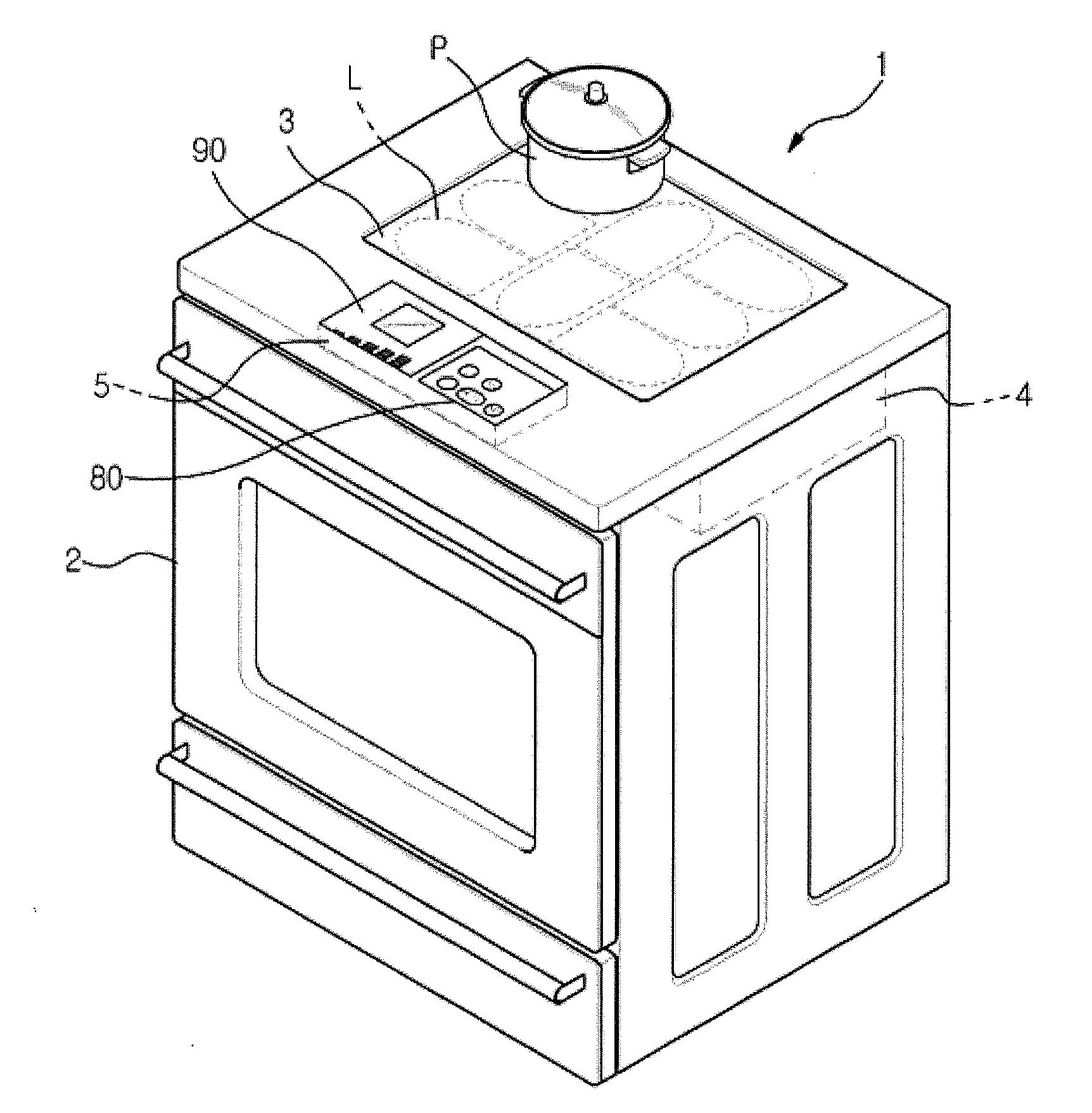
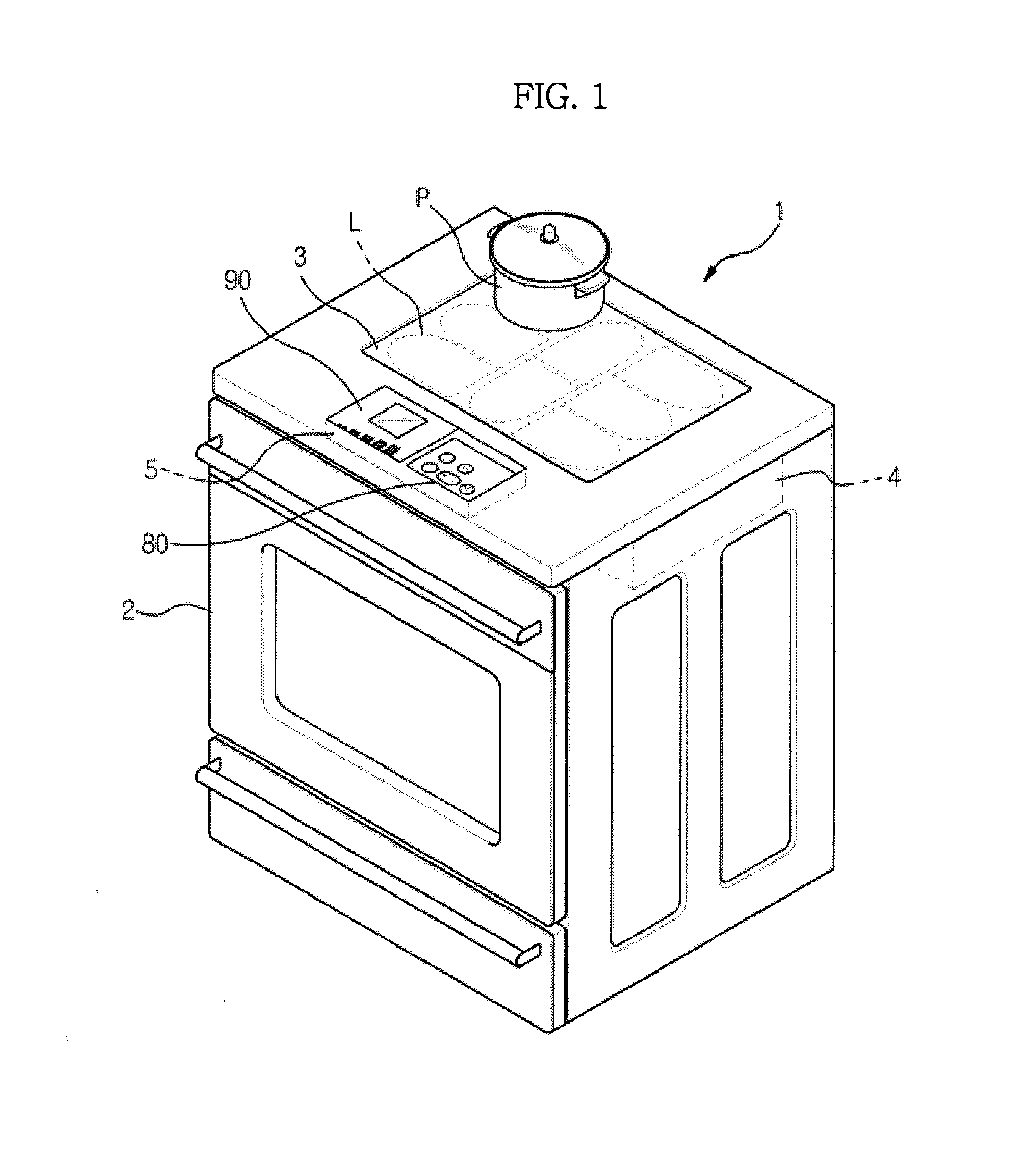
[0053]FIG. 1 is a perspective view illustrating the configuration of an induction heating cooker according to an embodiment of the present disclosure.

[0054]Referring to FIG. 1, an induction heating cooker 1 includes a body 2.

[0055]A cooking plate 3 configured to place a vessel (P) is installed on the body 2.

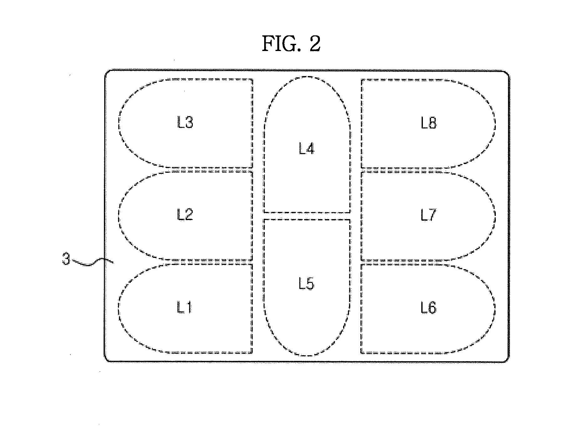
[0056]A plurality of heating coils (L) is provided inside the body 2 below the cooking plate 3 to provide a heat source. The heating coils (L) are densely disposed while being adjacent to one another over the entire surface of the cooking plate 3. As an example, the description of the heating coils (L) will be described in relation that the heating coils (L) include eight heating coils (L) disposed on the induction heating cooker 1.

[0057]In addition, a control appa...


PUM


Abstract

An induction heating cooker including a cooking plate on which a cooking vessel is placed, a plurality of heating coils disposed while being adjacent to one other below the cooking plate, and a Printed Circuit Board (PCB) on which circuits configured to drive the heating coils are placed, wherein the PCB is divided into a high frequency circuit part on which circuits characterized by high frequency are placed and a low frequency circuit part on which circuits characterized by low frequency are placed, and the high frequency circuit part is spaced apart from the low frequency circuit part by a predetermined distance. The interference between the high frequency circuit part and the low frequency circuit part is minimized while enhancing the operation efficiency of each heating coil. The assembly efficiency and the working efficiency are enhanced when an inverter circuit is wired to a corresponding heating coil.

Description

CROSS-REFERENCE TO RELATED APPLICATIONS[0001]This application claims the benefit of Korean Patent Application No. 2011-0027798, filed on Mar. 28, 2011 in the Korean Intellectual Property Office, the disclosure of which is incorporated herein by reference.BACKGROUND[0002]1. Field[0003]Embodiments of the present disclosure relate to an induction heating cooker capable of heating a vessel that is disposed at any place on a cooking plate.[0004]2. Description of the Related Art[0005]In general, an induction heating cooker is an apparatus configured to cooking foods by supplying a high frequency current to a heating coil to generate a high frequency magnetic field and by causing eddy currents in a cooking vessel (hereinafter referred to as a vessel) having a magnetic coupling with the cooking coil through the generated magnetic field such that the vessel is heated by Joule's heat generated through the eddy current to cook foods.[0006]Inside a body, which forms an external appearance of an...

Claims


Application Information

Patent Timeline
Patent Type & Authority Applications(United States)
IPC IPC(8): H05B6/12
CPCH05B6/1263H05B6/1272Y02B40/126H05B2213/03H05B2206/022Y02B40/00H05B6/02H05B6/12
Inventor LEE, SUNG HOSHON, JONG CHULLJUNG, MIN GYUKIM, HA NA
Owner SAMSUNG ELECTRONICS CO LTD
Why Eureka
Try Eureka