Creamy foam beer dispensing system

a beer dispensing system and foam technology, applied in the direction of liquid transferring devices, liquid handling, instruments, etc., can solve the problems of beer dispensing system off-taste, unsanitary conditions, labor-intensive cleaning, etc., to facilitate beer flow, facilitate gas flow, and prevent beer flow

Active Publication Date: 2012-10-04
LANCER PARTNERSHIP
View PDF32 Cites 19 Cited by
  • Summary
  • Abstract
  • Description
  • Claims
  • Application Information

AI Technical Summary

Benefits of technology

[0008]The faucet further includes a first housing body defining the compression tube receiver and a plunger shaft communicating with the compression tube receiver and adapted to receive at least a portion of the plunger therein. The first housing body includes a stage therein adjacent to the compression tube receiver. The compression tube receiver includes a taper that contacts a stop on the compression tube to arrest the insertion of the compression tube into the compression tube receiver. The plunger includes a plunger head normally biased against the compression tube in the closed position whereby the plunger head squeezes the compression tube against the stage such that no beer flows from the faucet. The plunger head includes a groove such that, in the creamy foam position, the groove of the plunger head facilitates creation of the aperture that produces creamy foam flow from the faucet. The faucet further comprises a second housing body that supports the first housing body therein.
[0010]The coupler includes a body having a top end, a keg engagement end engageable with the keg, and a bore therethrough. The fitment of the transportation tube removably inserts through the top end and into the bore. The coupler further includes a lever pivotally connected with the body, wherein the lever is movable from a disengaged position to an engaged position that pushes the fitment downward within the bore such that the fitment opens a keg valve assembly thereby facilitating beer flow from the keg through the transportation tube. The body further includes a gas inlet communicating with the bore, wherein opening of the keg valve assembly by the fitment facilitates gas flow through the bore and into the keg. The coupler still further includes a spring pin that maintains the fitment within the bore.
[0011]The creamy foam beer dispensing system further includes a refrigeration module having a body adapted to receive a keg therein. The body includes a top with an opening, and a tower mounted onto the top of the body over the opening such that cool air from the body flows into the tower. The faucet mounts to the tower and includes a passage therethrough communicating with the tower such that cool air flows from the tower through the faucet thereby cooling the faucet.
[0013]Replacing a used transportation tube with a new transportation tube is accomplished as follows. First, the coupler le vet is moved from its engaged position to its disengaged position such that the fitment of the transportation tube releases the keg valve assembly thereby preventing beer flow from the keg through the transportation tube. Second, the fitment is removed from the top end of the coupler and the transportation tube is removed from the faucet. Third, the transportation tube is removed from a tower of the beer dispensing system and the removed transportation tube is disposed. Fourth, a new transportation Lube is inserted into the tower of the beer dispensing system. Fifth, a beer dispensing end of the new transportation tube is inserted into the faucet, and a fitment of the new transportation tube is inserted through the top end of the coupler and into the bore of the coupler. Finally, the coupler lever is moved from its disengaged position to its engaged position, whereby the lever pushes the fitment downward within the bore such that the fitment opens the keg valve assembly thereby facilitating beer flow from the keg through the transportation tube.

Problems solved by technology

Although two path faucets operate adequately, they are complicated and costly to manufacture.
Moreover, cleaning is labor intensive and, if not performed often or properly, leads to off-taste and unsanitary conditions in the beer dispensing system.

Method used


Image

  • Creamy foam beer dispensing system
  • Creamy foam beer dispensing system
  • Creamy foam beer dispensing system

Examples


Embodiment Construction

[0023]As required, detailed embodiments of the present invention are disclosed herein; however, it is to be understood that the disclosed embodiments are merely exemplary of the invention, which may be embodied in various forms. Figures are not necessarily to scale, and some features may be exaggerated to show details of particular components or steps.

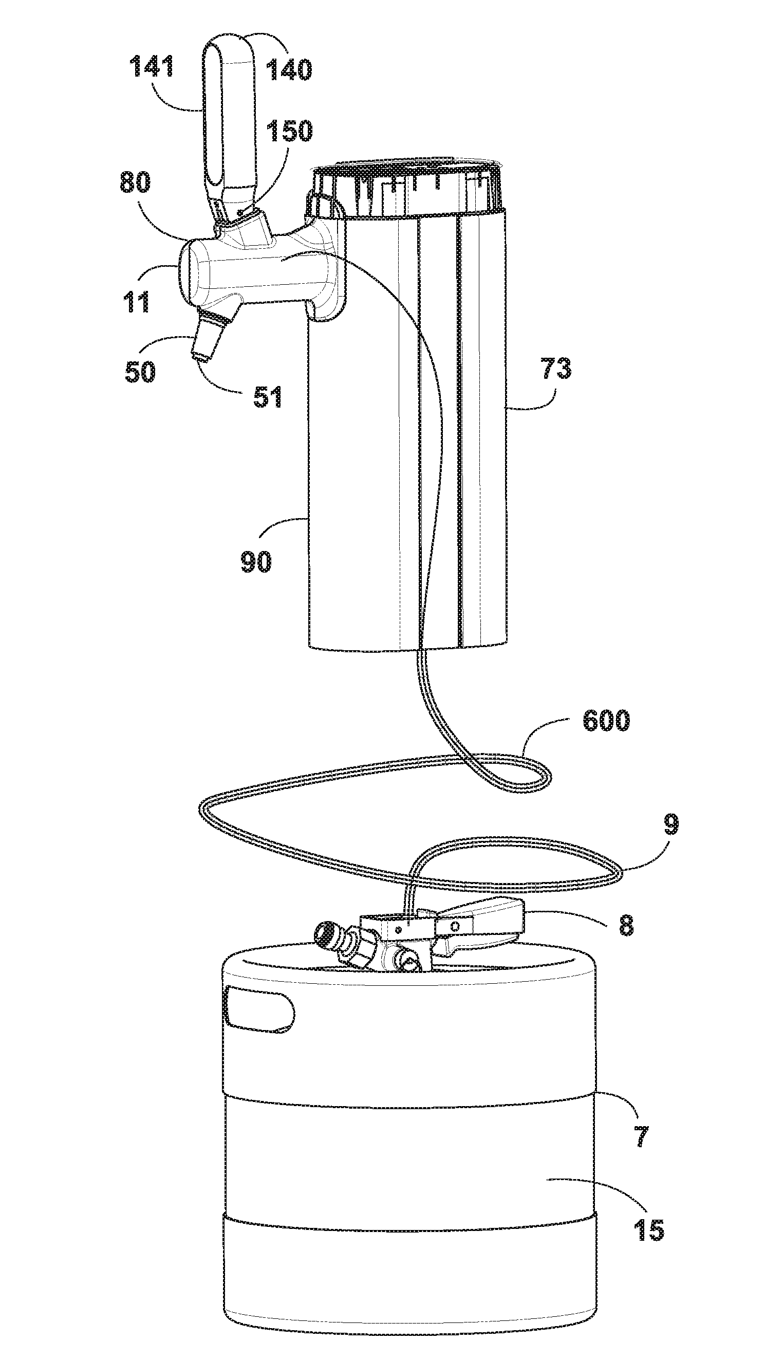
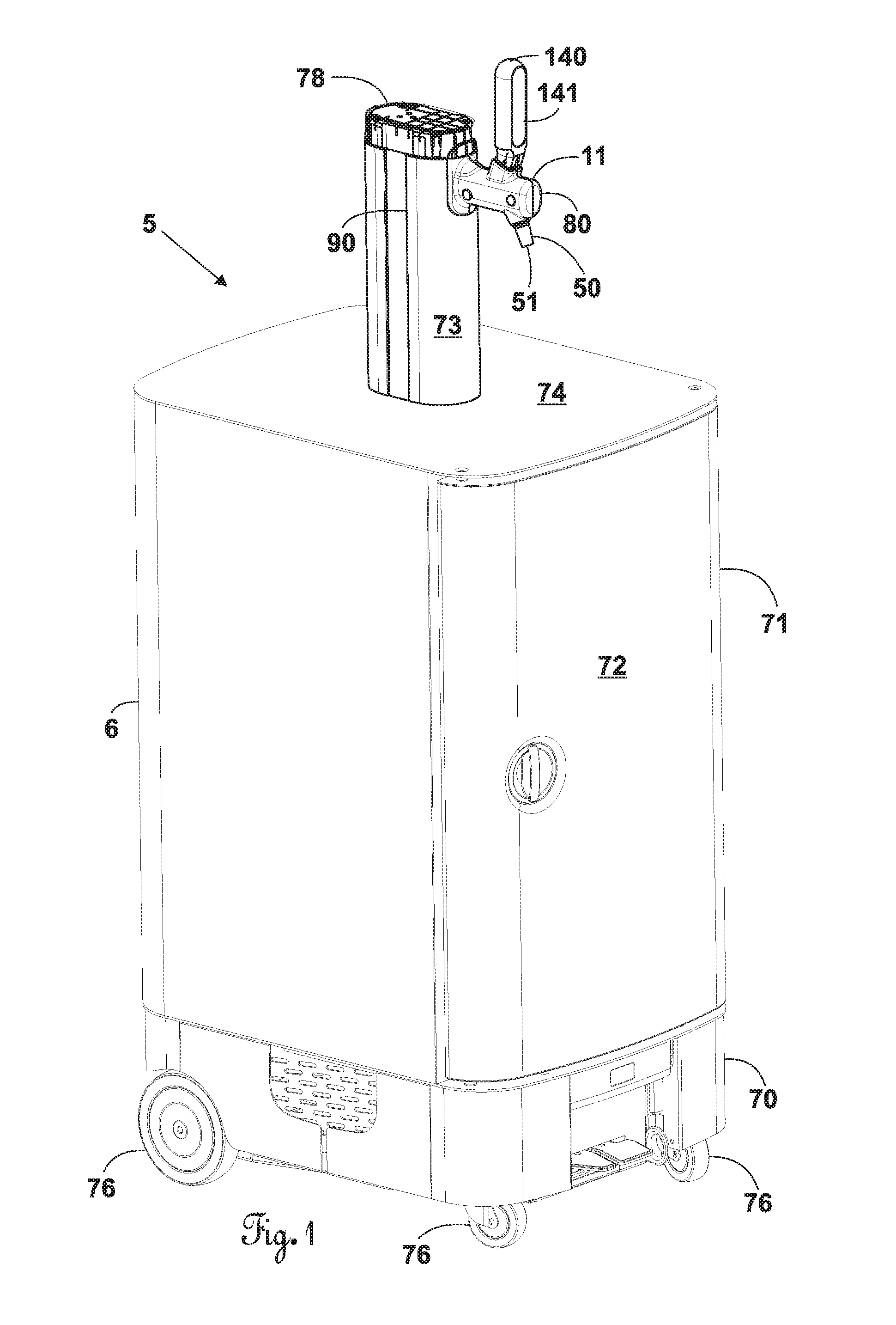
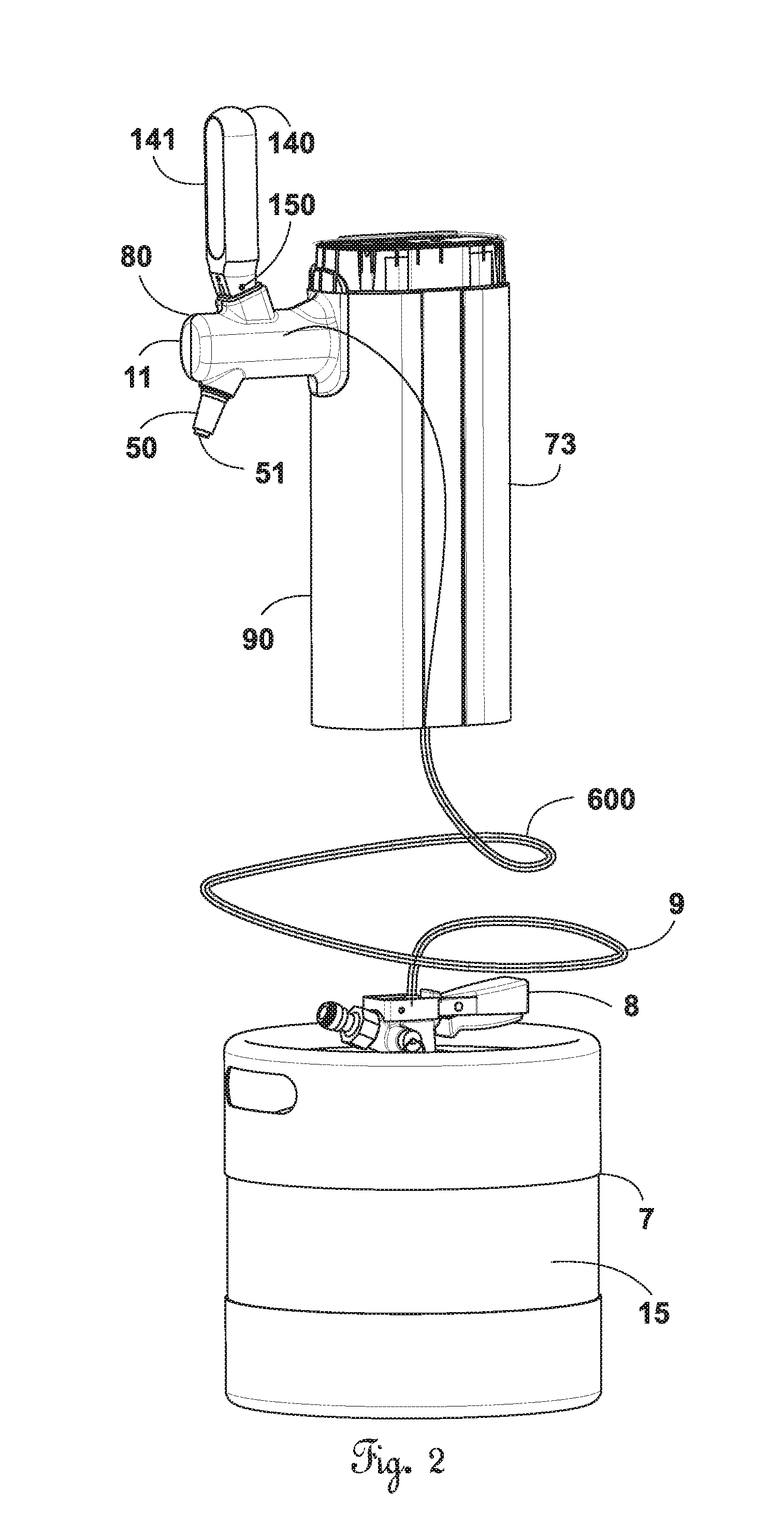
[0024]The Figures illustrate a creamy foam beer dispensing system 5 according to the preferred. embodiment of the present invention. The creamy foam beer dispensing system 5 delivers beer from a keg 7 and includes a refrigeration module 6, a transportation tube 9, a coupler 8, and a faucet 11.

[0025]FIG. 1 illustrates the refrigeration module 6. The refrigeration module 6 includes a base 70, a body 71, a door 72, and a tower 73. The base 70 has wheels 76 that allow the refrigeration module 6 to be easily moved. The body 71 mounts on the base 70 while the door 72 attaches to the body 71. The body 71 and the door 72 define a chamber that ...


PUM

PropertyMeasurementUnit
temperatureaaaaaaaaaa
lengthaaaaaaaaaa
distanceaaaaaaaaaa

Abstract

A creamy foam beer dispensing system includes a coupler removably securable with a keg, a transportation tube, and a faucet having a handle coupled with a plunger communicating with the transportation tube. The handle is movable among a closed position, an open position, and a creamy foam position. In the closed position, the handle maintains the plunger squeezed against the transportation tube such that no beer flows from the faucet. In the open position, the handle lifts the plunger substantially, completely off the transportation tube such that beer flows smoothly from the faucet. In the creamy foam position, the handle lifts the plunger off the transportation tube a distance such that an aperture created in the transportation tube produces creamy foam flow from the faucet.

Description

CROSS-REFERENCE TO RELATED APPLICATION[0001]This present application claims all available benefit, under 35 U.S.C. §119(e), of U.S. provisional patent application Ser. No. 61 / 516,210 filed Mar. 31, 2011. By this reference, the full disclosure of U.S. provisional patent application Ser. No. 61 / 516,210 is incorporated herein as though now set forth in its entirety.BACKGROUND OF THE INVENTION[0002]1. Field of the Invention[0003]The present invention relates to a beer dispensing system. More particularly, the beer dispensing system allows an operator to pour beer with or without creamy foam. In addition, the components of the beer dispensing system contacted by dispensed beer are disposable thereby removing the need for sanitation.[0004]2. Description of the Related Art[0005]In many parts of the world, consumers desire creamy foam on top of their beer. As such, beer dispensers that pour beer smoothly without foam followed by the ability to add creamy foam on top have been developed. The...

Claims


Application Information

Patent Timeline
Patent Type & Authority Applications(United States)
IPC IPC(8): B65D47/00B67D7/00
CPCB67D1/1411Y10T29/4973B67D1/0829B67D1/0835B67D1/0841Y10T137/6137Y10T137/2984Y10T137/314B67D1/0848
Inventor HASKAYNE, PAULSHETTLE, ROBERT W.SMELLER, DONLAD W.JENNINGS, III, JARRELL L.GOOD, MERRILL R.
Owner LANCER PARTNERSHIP
Why Eureka
Try Eureka