Power management in energy buffered building control unit

a technology for building control units and power management, applied in the direction of program control, heating types, instruments, etc., can solve the problems of difficult and costly direct hardwiring of “common” wires from transformers to electronic thermostats, disadvantages of using batteries for providing operating power, and need to continually check and replace batteries

Active Publication Date: 2012-10-04
GOOGLE LLC
View PDF6 Cites 80 Cited by
  • Summary
  • Abstract
  • Description
  • Claims
  • Application Information

AI Technical Summary

Benefits of technology

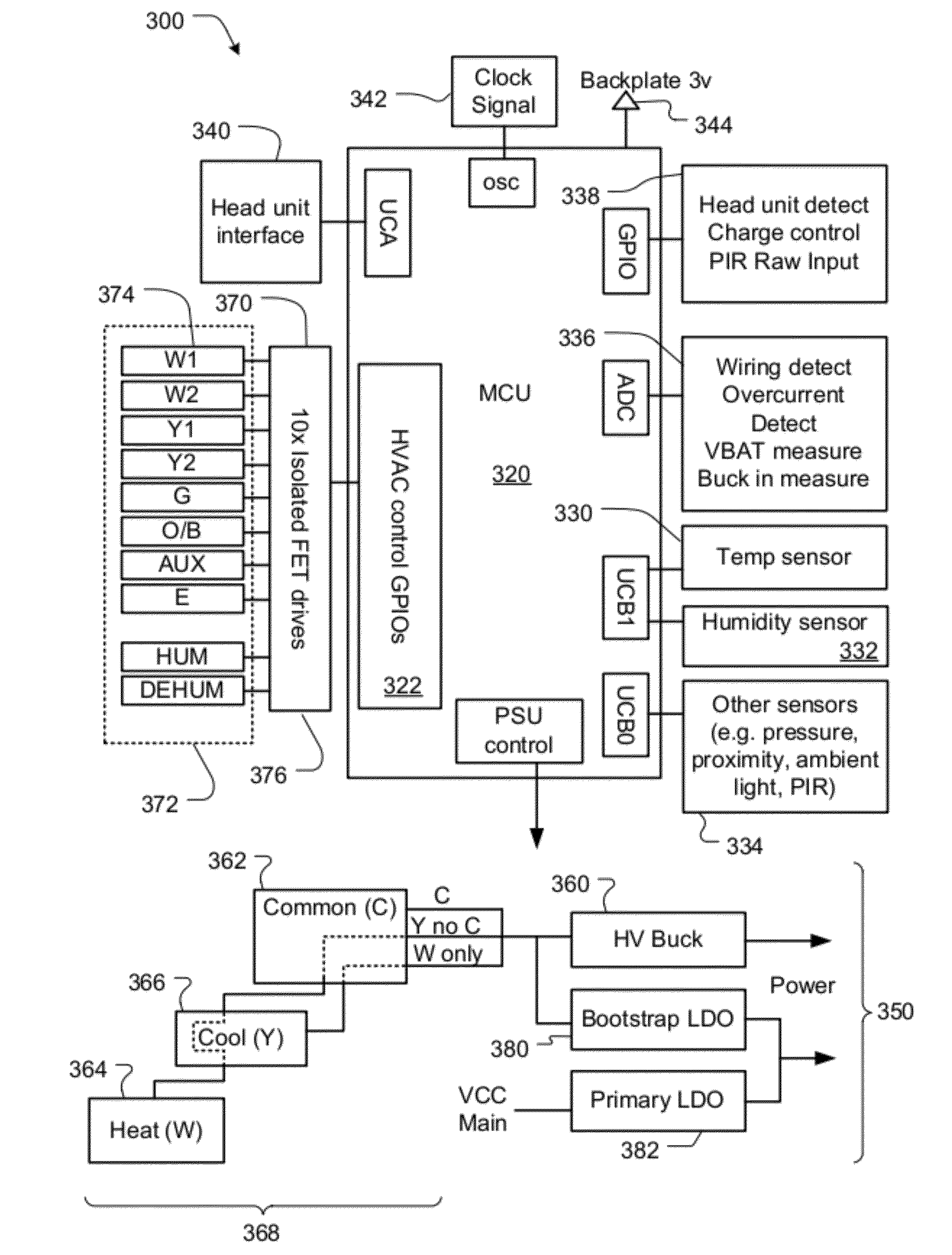
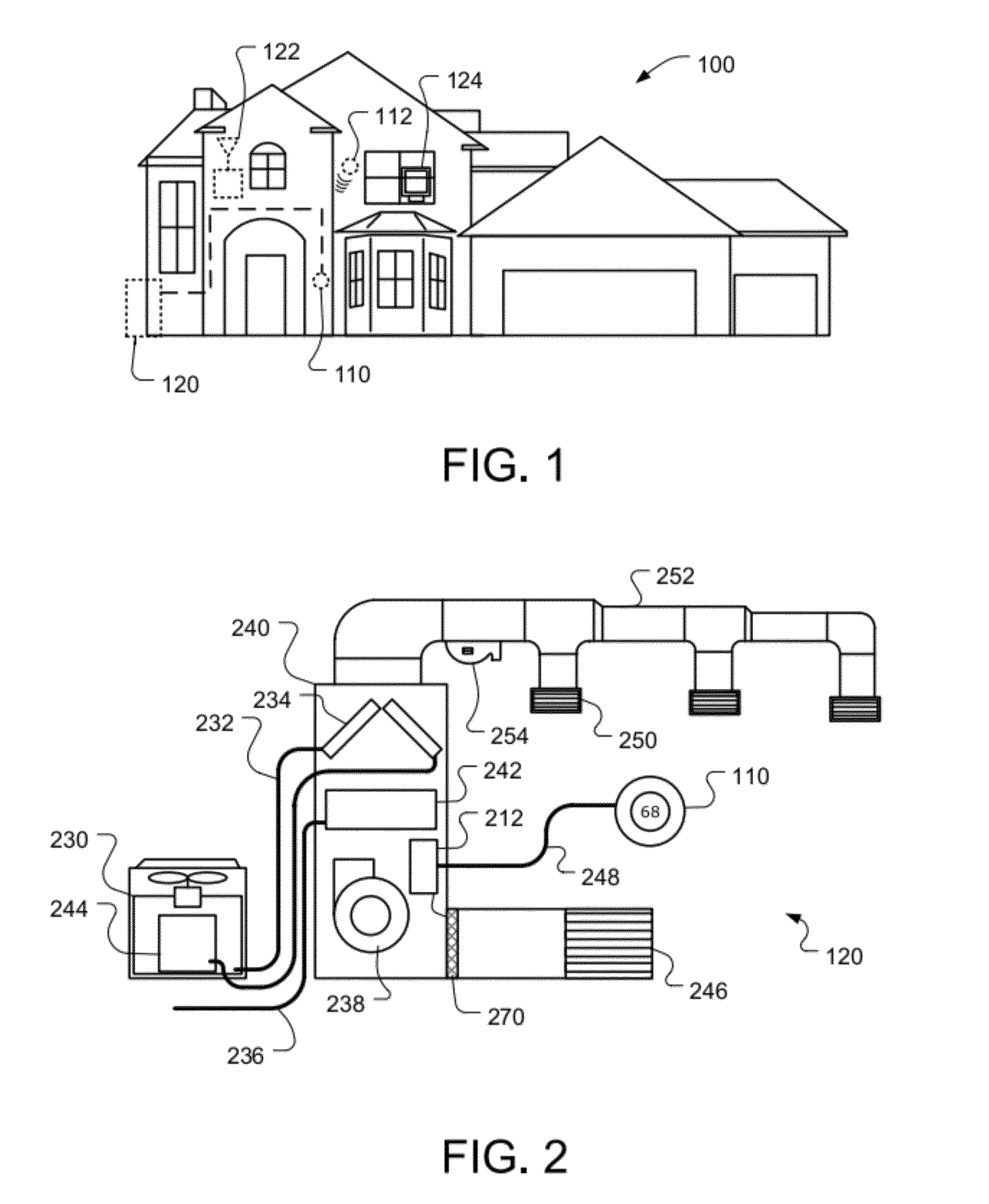
[0011]This patent specification relates to systems and methods for the monitoring and control of energy-consuming systems or other resource-consuming systems. More particularly, this patent specification relates control units that govern the operation of energy-consuming systems, household devices, or other resource-consuming systems, including methods for providing electrical power for thermostats that govern the operation of heating, ventilation, and air conditioning (HVAC) systems. In a preferred embodiment, the thermostat includes selected feature combinations that have been found to be advantageous for the facilitation of do-it-yourself thermostat installation, the accommodation of a variety of different practical installation scenarios (including scenarios where a “C” power wire is not available), the provisioning of relatively power-intensive advanced interfaces and functionalities (e.g., a large visually pleasing electronic display, a relatively powerful general purpose microprocessor, and a reliable Wi-Fi communications chip) even where a “C” power wire is not available, the facilitation of operational robustness and durability, compact device size, quietness of operation, and other advantageous characteristics described in the instant disclosure and / or the commonly assigned incorporated applications.

Problems solved by technology

When electronics began to be used in thermostats the fact that the thermostat was not directly wired to both sides of the transformer for its power source created a problem.
Direct hardwiring a “common” wire from the transformer to the electronic thermostat may be very difficult and costly.
However, there are also disadvantages to using a battery for providing the operating power.
One primary disadvantage is the need to continually check and replace the battery.
If the battery is not properly replaced and cannot provide adequate power, the electronic thermostat may fail during a period of extreme environmental conditions.
However, these systems do not have power storage means and therefore must always rely on power stealing or must use disposable batteries.

Method used


Image

  • Power management in energy buffered building control unit
  • Power management in energy buffered building control unit
  • Power management in energy buffered building control unit

Examples


Embodiment Construction

[0043]The subject matter of this patent specification relates to the subject matter of the following commonly assigned applications, each of which is incorporated by reference herein:

[0044]U.S. Ser. No. 12 / 881,430 filed Sep. 14, 2010; U.S. Ser. No. 12 / 881,463 filed Sep. 14, 2010; U.S. Prov. Ser. No. 61 / 415,771 filed Nov. 19, 2010; U.S. Prov. Ser. No. 61 / 429,093 filed Dec. 31, 2010; U.S. Ser. No. 12 / 984,602 filed Jan. 4, 2011; U.S. Ser. No. 12 / 987,257 filed Jan. 10, 2011; U.S. Ser. No. 13 / 033,573 filed Feb. 23, 2011; U.S. Ser. No. 29 / 386,021, filed Feb. 23, 2011; U.S. Ser. No. 13 / 034,666 filed Feb. 24, 2011; U.S. Ser. No. 13 / 034,674 filed Feb. 24, 2011; U.S. Ser. No. 13 / 034,678 filed Feb. 24, 2011; U.S. Ser. No. 13 / 038,191 filed Mar. 1, 2011; U.S. Ser. No. 13 / 038,206 filed Mar. 1, 2011; U.S. Ser. No. 29 / 399,609 filed Aug. 16, 2011; U.S. Ser. No. 29 / 399,614 filed Aug. 16, 2011; U.S. Ser. No. 29 / 399,617 filed Aug. 16, 2011; U.S. Ser. No. 29 / 399,618 filed Aug. 16, 2011; U.S. Ser. No. 29...


PUM


Abstract

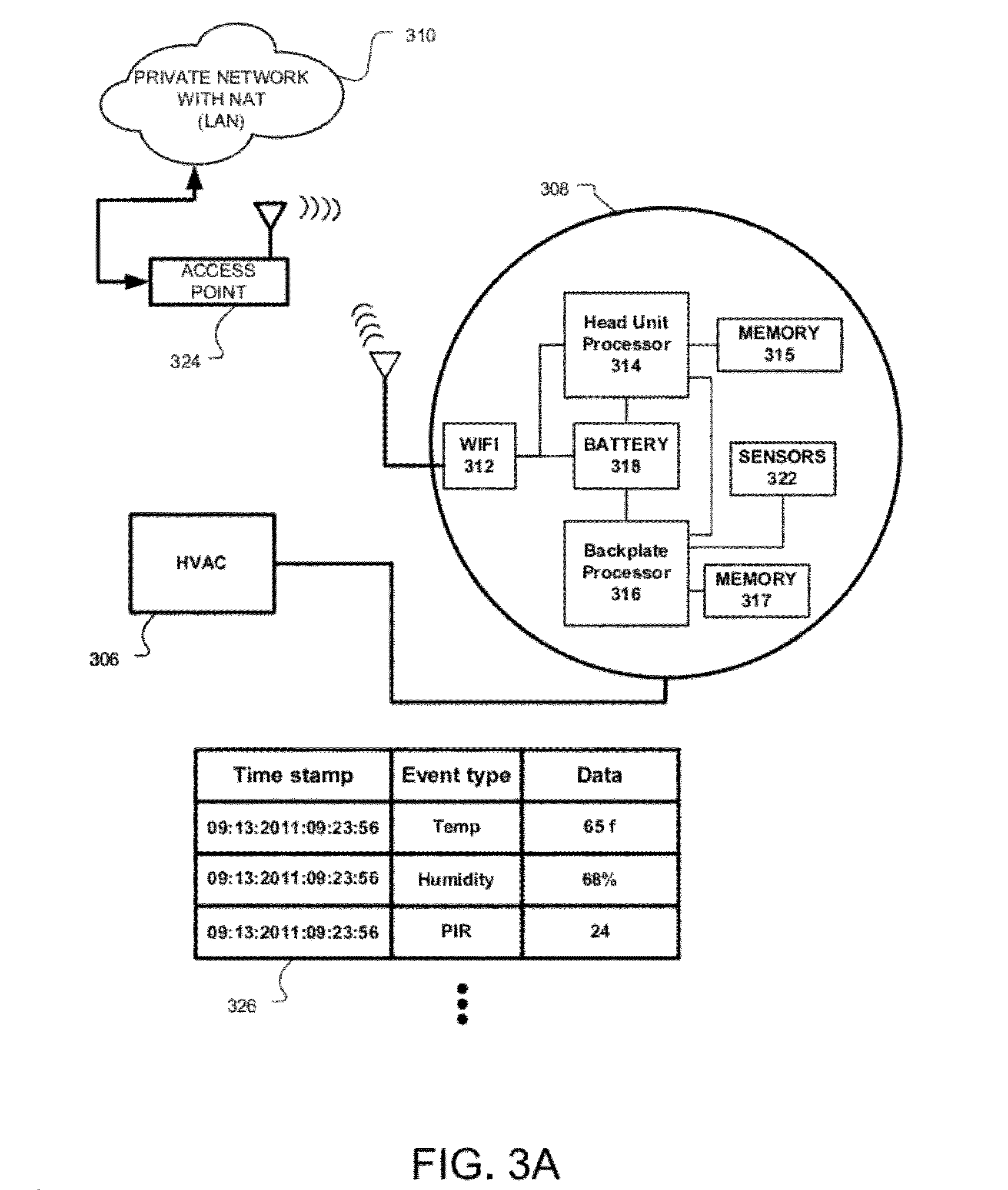
A thermostat includes a plurality of HVAC (heating, ventilation, and air conditioning) wire connectors for receiving a plurality of HVAC control wires corresponding to an HVAC system. The thermostat also includes a thermostat processing and control circuit configured to at least partially control the operation of the HVAC system and a powering circuit coupled to the HVAC wire connectors and configured to provide an electrical load power to the thermostat processing and control circuit. The powering circuit has a power extraction circuit configured to extract electrical power from one or more of the plurality of received HVAC control wires up to a first level of electrical power, a rechargeable battery, and a power control circuit coupled to the power extraction circuit, the rechargeable battery, and the thermostat processing and control circuit. The power control circuit is configured to provide the electrical load power using power from the power extraction circuit and the rechargeable battery.

Description

CROSS-REFERENCES TO RELATED APPLICATIONS[0001]This patent application claims the benefit of U.S. Provisional Application No. 61 / 627,996 (Attorney Docket No. NES0101-PROV) filed Oct. 21, 2011.[0002]This application is also a continuation-in-part of the following commonly-assigned applications: PCT Application No. PCT / US11 / 61437, (Attorney Docket No. NES0101-PCT) filed Nov. 18, 2011; U.S. patent application Ser. No. 13 / 267,877, (Attorney Docket No. NES0100-US), filed Oct. 6, 2011; U.S. Ser. No. 13 / 034,674 (Attorney Docket No. NES0006-US) filed Feb. 24, 2011; and U.S. Ser. No. 13 / 034,678 (Attorney Docket No. NES0007-US) filed Feb. 24, 2011.[0003]Each of the above-referenced patent applications is incorporated herein by reference in its entirety for all purposes.TECHNICAL FIELD[0004]This patent specification relates to systems and methods for the monitoring and control of energy-consuming systems or other resource-consuming systems. More particularly, this patent specification relates c...

Claims


Application Information

Patent Timeline
Patent Type & Authority Applications(United States)
IPC IPC(8): G05D23/19
CPCF24F11/0012F24F2011/0036F24F2011/0068F24F2011/0073G05B2219/2642G05D23/19F24D19/1087G05B2219/2614G05D23/1902F24F11/30F24F2110/10F24F2120/14F24F11/56F24F11/61F24F11/52F24F11/58F24F11/88F24F2120/00F24F11/46F24F11/66
Inventor WARREN, DANIEL ADAMFIENNES, HUGODUTRA, JONATHAN ALANBELL, DAVIDFADELL, ANTHONY MICHAELROGERS, MATTHEW LEESMITH, IAN C.SATTERTHWAITE, JR., EDWIN H.PALMER, JOSEPH E.ERICKSON, GRANT M.MUCIGNAT, ANDREA
Owner GOOGLE LLC
Why Eureka
Try Eureka