Aircraft fuselage with high strength frames

a fuselage and frame technology, applied in the field of aircraft fuselages, can solve problems such as manufacturing problems, and achieve the effect of high-resistance aircraft fuselage structures

Active Publication Date: 2012-10-04
AIRBUS OPERATIONS SL
View PDF22 Cites 10 Cited by
  • Summary
  • Abstract
  • Description
  • Claims
  • Application Information

AI Technical Summary

Benefits of technology

[0012]It is an object of the present invention to pr

Problems solved by technology

Open section shaped frames such as the frames used in U.S. Pat. No. 5,242,523 are indeed convenient from a manufacturing point of view although re

Method used


Image

  • Aircraft fuselage with high strength frames
  • Aircraft fuselage with high strength frames
  • Aircraft fuselage with high strength frames

Examples


Embodiment Construction

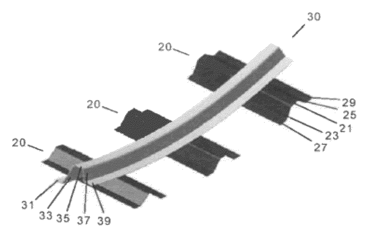
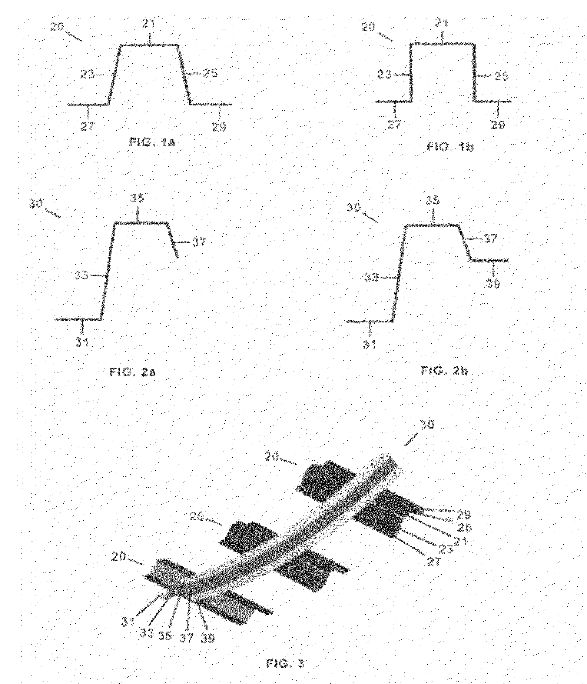
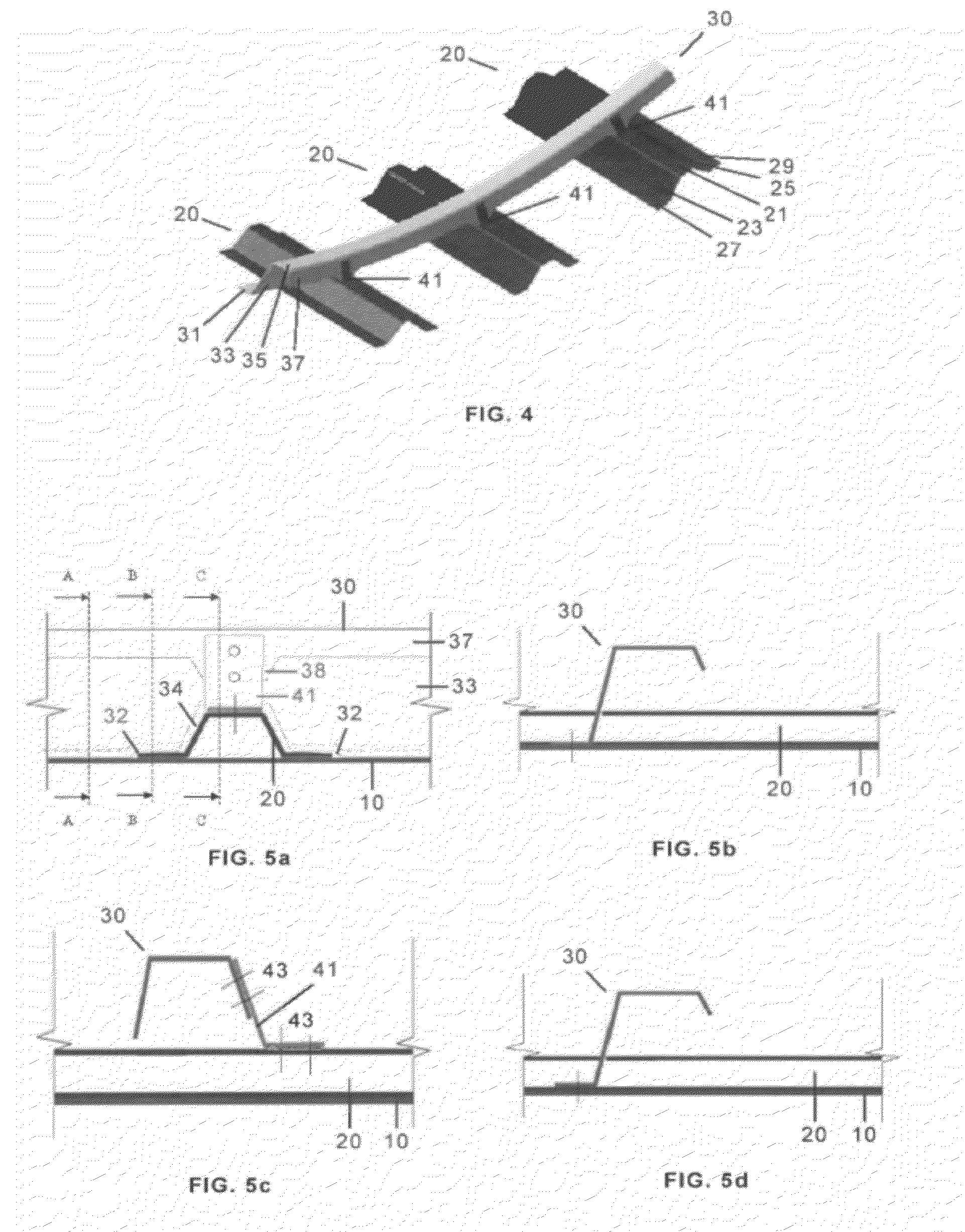
[0034]The main structural elements of an aircraft fuselage according to this invention are the skin, closed-shaped longitudinal stringers and S-shaped circumferential frames that can be made of metallic or composite materials.

[0035]Within the meaning of this invention a close-shaped stringer is a stringer 20 having a closed transversal section, as the omega-shaped section shown in FIG. 1a or the π-shaped section shown in FIG. 1b, configured by a hat 21, two webs 23, 25 and two feet 27, 29 to be joined to the skin of the fuselage, and an S-shaped frame is a frame 30 having a semi-closed transversal section configured as shown in FIG. 2a by a foot 31 to be joined to the skin 10, a web 33 at an angle with the foot 31 comprised between 90° and 170°, a cap 35 and a cap extension 37 at an angle with the cap comprised between 90° and 170°. It can also include a second foot 39 further to the cap extension 37 as shown in FIG. 2b.

[0036]One embodiment of the invention is shown in FIG. 3 where...


PUM


Abstract

Fuselage section of an aircraft whose structure comprises a skin (10), a plurality of frames (30) positioned transversely to the longitudinal axis of the fuselage and a plurality of longitudinal stringers (20); the stringers being configured with a closed transversal section comprising a hat (21), two webs (23, 25) and two feet (27, 29) joined to the skin (10); the frames (30) being configured in at least one its sectors with a foot (31) joined to the skin (10), a web (33) having holes at the crossing zones with said stringers (20), a cap (35) and a cap extension (37) which does not interfere with the stringers (20); the frames (30) being joined to, at least, the stringer hats (21) at their crossing zones.

Description

FIELD OF THE INVENTION[0001]The present invention refers to an aircraft fuselage and more particularly to an aircraft fuselage with high strength frames.BACKGROUND OF THE INVENTION[0002]The aeronautical industry requires structures which, on the one hand, support the loads to which they are subjected fulfilling high stiffness and resistance demands and, on the other hand, are as light as possible. A consequence of this requirement is the continuously expanding use of composite materials in primary structures because, by conveniently applying these materials, an important weight reduction can be achieved compared with structures designed with metallic materials.[0003]The composite materials that are most used in the aeronautical industry consist of fibers or fiber bundles embedded in a matrix of thermosetting or thermoplastic resin, in the form of a preimpregnated or “prepreg” material. Its main advantages refer to:[0004]Their high specific strength with respect to metallic materials...

Claims


Application Information

Patent Timeline
IPC IPC(8): B64C1/06
CPCB64C1/12B64C1/064
Inventor VINUE SANTOLALLA, EDUARDOFOLCH CORTES, DIEGOMARTINO GONZALEZ, ESTEBANGUINALDO FERNANDEZ, ENRIQUEGOYA ABAURREA, PABLO
Owner AIRBUS OPERATIONS SL
Why Eureka
Try Eureka