
Method and apparatus for improving the operation of an auxiliary power system of a thermal power plant

a technology of auxiliary power system and thermal power plant, which is applied in the direction of emergency power supply arrangement, transportation and packaging, electric vehicles, etc., can solve the problems of reducing apparent power and loss for the same amount of real power transfer, and reducing overall transmission efficiency

Inactive Publication Date: 2012-10-04
ABB RES LTD
View PDF0 Cites 18 Cited by
  • Summary
  • Abstract
  • Description
  • Claims
  • Application Information

AI Technical Summary

Benefits of technology

"The present invention provides a computer-readable medium and apparatus for controlling power in an auxiliary power system of a thermal power plant. The method includes monitoring the voltage of each auxiliary bus and controlling the power factor of the system to have a predetermined value. When a voltage disturbance occurs, the control is stopped and the voltage is controlled to move back into the predetermined range. The control includes increasing or decreasing the reactive power of the adjustable speed drives connected to the affected auxiliary bus. The technical effect of this invention is to improve the stability and efficiency of the auxiliary power system of a thermal power plant."

Problems solved by technology

These higher currents in a power system will produce higher losses and reduce overall transmission efficiency.
A lower power factor circuit will have a higher apparent power and higher losses for the same amount of real power transfer.
However, many base load power plants now often operate at only 50-70% of their rated capacities due to the increased presence of renewable energy sources (e.g. wind mill farms), increased system operating reserve requirements and competitive energy markets.
Even when a power plant is running at full capacity, pumps and fans typically do not run at their rated capacity because of required design margins.

Method used


Image

  • Method and apparatus for improving the operation of an auxiliary power system of a thermal power plant
  • Method and apparatus for improving the operation of an auxiliary power system of a thermal power plant
  • Method and apparatus for improving the operation of an auxiliary power system of a thermal power plant

Examples


Embodiment Construction

[0016]It should be noted that in the detailed description that follows, identical components have the same reference numerals, regardless of whether they are shown in different embodiments of the present invention. It should also be noted that in order to clearly and concisely disclose the present invention, the drawings may not necessarily be to scale and certain features of the invention may be shown in somewhat schematic form.

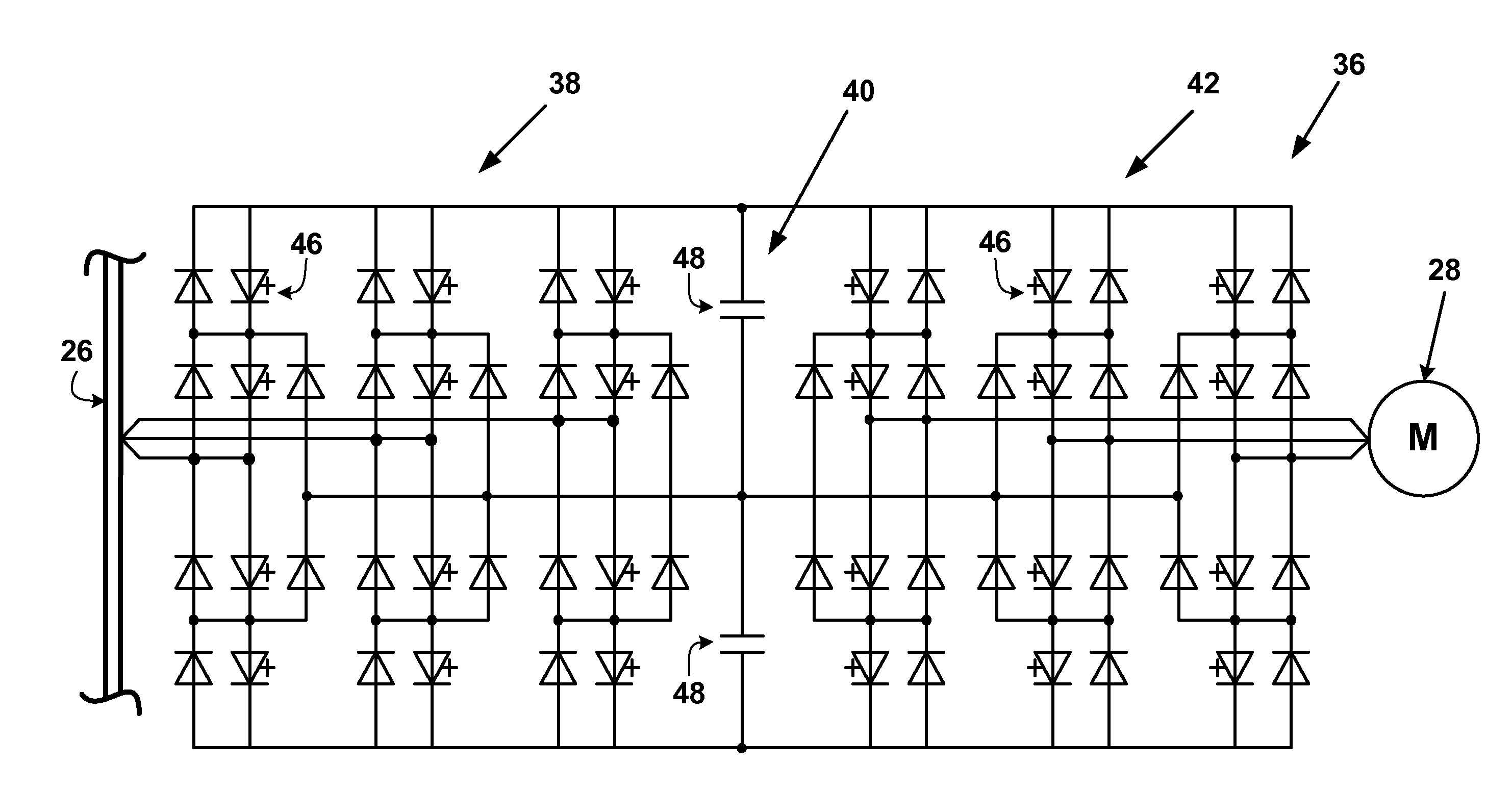
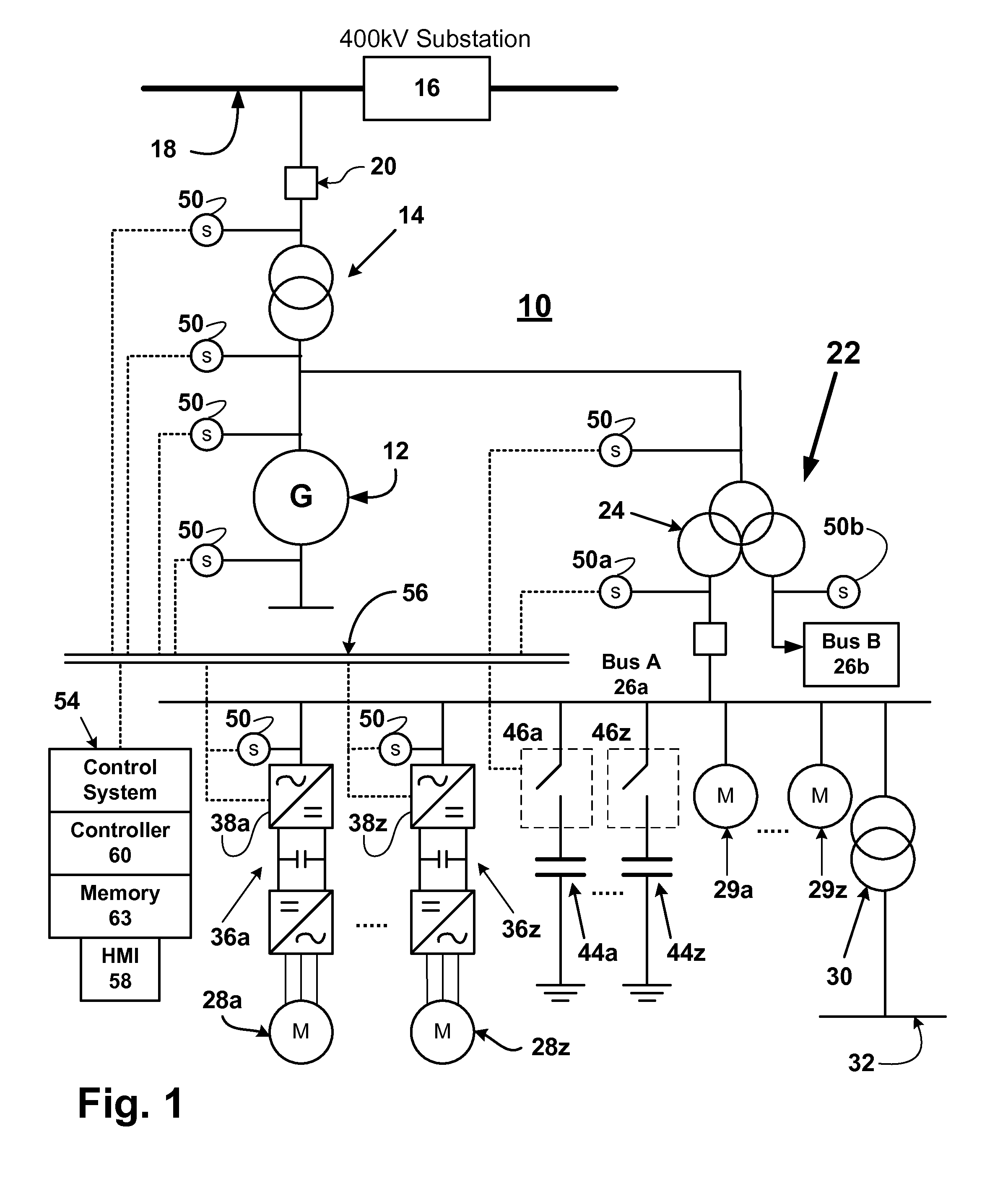
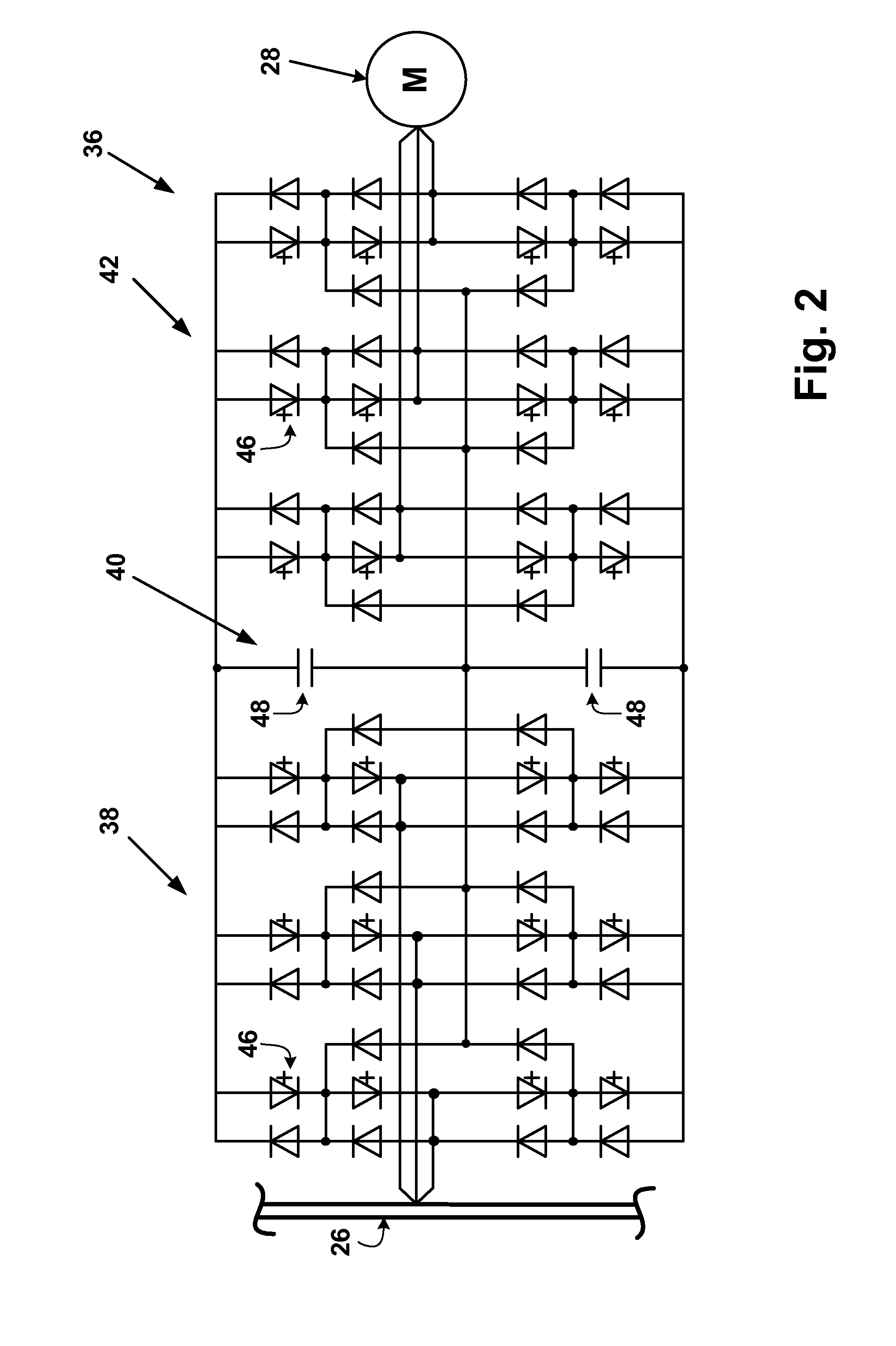
[0017]Referring now to FIG. 1 there is shown a schematic drawing of a power generation plant 10 in which the method and apparatus of the present invention may be utilized. The generation plant 10 may be a thermal power plant, such as a coal-fired power plant, a nuclear power plant, a solar power plant, or a geothermal power plant. The generation plant 10 includes a generator 12 that generates electricity from mechanical energy supplied by one or more steam-driven turbines (not shown). A step-up main transformer 14 converts the electrical power from the gener...


PUM


Abstract

Apparatus and method for controlling power in an auxiliary power system of a thermal power plant having a generator and one or more auxiliary buses. The apparatus includes adjustable speed drives and capacitance sources for connection to the one or more auxiliary buses and sensors for measuring voltage and reactive power on the one or more auxiliary buses. A controller is operable to control the adjustable speed drives and the capacitance sources to control the power factor of the auxiliary power system, while providing steady state voltage regulation and dynamic voltage support.

Description

BACKGROUND OF THE INVENTION[0001]The present invention relates to thermal power plants and more particularly to auxiliary power systems for such plants.[0002]The portion of power flow that results in a net transfer of energy in one direction (over a complete AC waveform cycle) is known as real power (or useful or active power). That portion of power flow that is due to stored energy in the load returning to the source in each cycle is known as reactive power. Apparent power is the vector sum of real and reactive power.[0003]The power factor of an AC power system is defined as the ratio of real power to apparent power, and is a number between 0 and 1. Where the waveforms are purely sinusoidal, the power factor is the cosine of the phase angle (φ) between the current and voltage sinusoid waveforms. Power factor equals 1 when the voltage and current are in phase, and is zero when the current leads or lags the voltage by 90 degrees. If the load is purely reactive, then the voltage and c...

Claims


Application Information

Patent Timeline
Patent Type & Authority Applications(United States)
IPC IPC(8): H02J9/00
CPCH02J9/00H02J11/00
Inventor PAN, JIUPINGCHEN, CATHY-YAOWANG, ZHENYUANGERTMAN, LARS
Owner ABB RES LTD
Learn More