Centrifugal heat dissipation device and motor using same

a centrifugal heat dissipation and motor technology, applied in the direction of lighting and heating apparatus, magnetic circuit rotating parts, magnetic circuit shapes/forms/construction, etc., can solve the problems of reducing the efficiency of the motor rotor, limiting the maximum power of the rotary motor, increasing the temperature, etc., to achieve enhanced vapor-liquid circulation and heat dissipation performance.

Inactive Publication Date: 2012-10-04
ASIA VITAL COMPONENTS SHENZHEN CO LTD
View PDF11 Cites 14 Cited by
  • Summary
  • Abstract
  • Description
  • Claims
  • Application Information

AI Technical Summary

Benefits of technology

[0008]A primary object of the present invention is to provide a centrifugal heat dissipation device that utilizes a centrifugal force to enable enhanced vapor-liquid circulation of a working fluid filled therein, so as to provide increased heat dissipation effect.
[0013]When the centrifugal heat dissipation device rotates along with the shaft of the motor, a centrifugal force is produced. The centrifugal force enables enhanced vapor-liquid circulation of a working fluid filled in the heat-absorption zone of the main body of the centrifugal heat dissipation device, so that heat generated by the operating motor is absorbed by the centrifugal heat dissipation device and transferred to the shaft for guiding out of the motor, allowing the motor to have largely upgraded heat dissipation performance.

Problems solved by technology

The hysteresis loss (iron loss) and copper loss of the rotor would generate thermal power, which causes increased temperature and lowered efficiency of the motor rotor, and thereby limits the maximum power of the rotary motor.
However, this type of heat transfer mechanism can only provide relatively small cooling effect.
Otherwise, the rotor rotating at high load is subject to burnout due to the thermal power generated by the hysteresis loss (iron loss) and copper loss.
As to the rotor, it could not be effectively cooled since there has not been any effective heat dissipation means for rotor up to date.
In brief, the prior art motors or power generators have the following disadvantages: (1) the hysteresis loss and copper loss of the rotor thereof generates thermal power to result in increased rotor temperature and limited motor power; (2) heat tends to accumulate in the rotor; and (3) the rotor has low cooling performance.

Method used


Image

  • Centrifugal heat dissipation device and motor using same
  • Centrifugal heat dissipation device and motor using same
  • Centrifugal heat dissipation device and motor using same

Examples


Embodiment Construction

[0037]The present invention will now be described with some preferred embodiments thereof and with reference to the accompanying drawings. For the purpose of easy to understand, elements that are the same in the preferred embodiments are denoted by the same reference numerals.

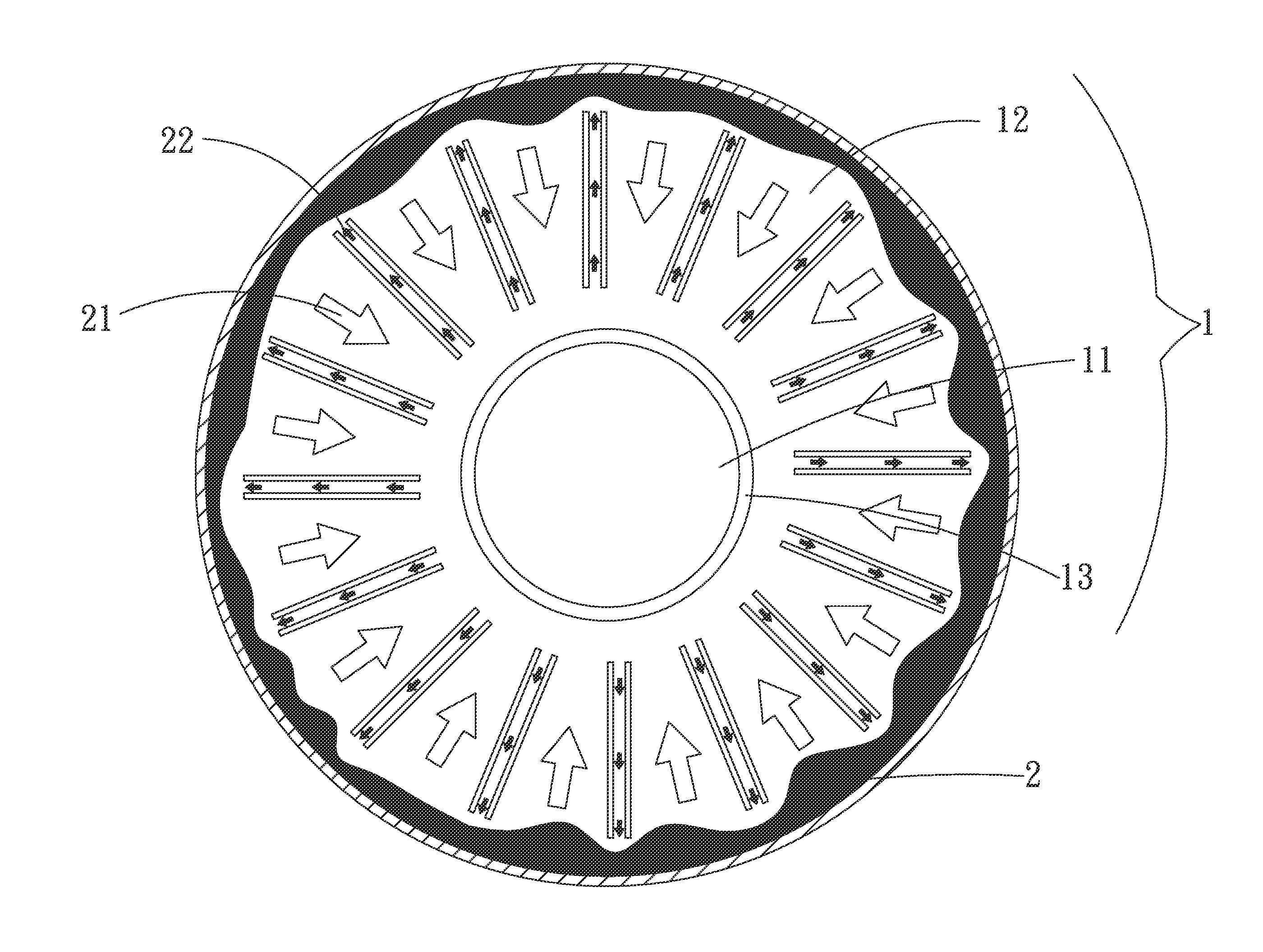
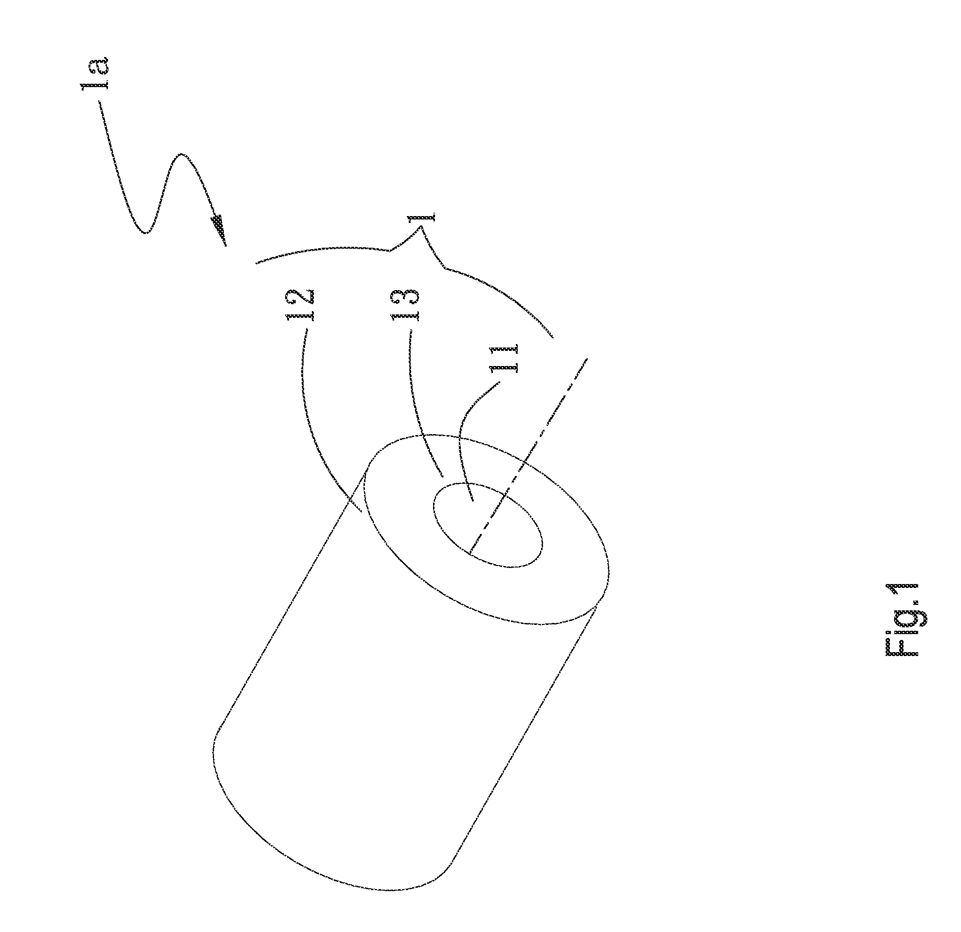
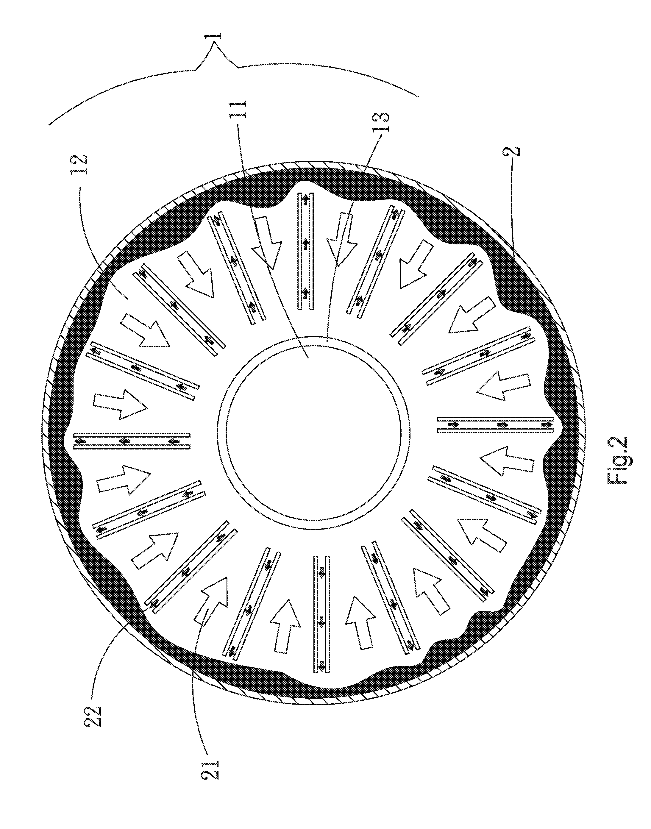
[0038]Please refer to FIGS. 1 and 2 that are assembled perspective view and cross sectional view, respectively, of a first embodiment of a centrifugal heat dissipation device 1a according to the present invention. As shown, the centrifugal heat dissipation device 1a in the first embodiment includes a cylindrical main body 1 having a shaft hole 11, a heat-absorption zone 12, and a heat-transfer zone 13. The heat-transfer zone 13 has a radially outer side connected to the heat-absorption zone 12 and a radially inner side connected to the shaft hole 11. The shaft hole 11 axially extends through the main body 1.

[0039]The heat-absorption zone 12 is internally provided with a working fluid 2.

[0040]Please refer to FIG...


PUM


Abstract

A centrifugal heat dissipation device and a motor using same are disclosed. The centrifugal heat dissipation device includes a main body having a shaft hole, a heat-absorption zone and a heat-transfer zone. The heat-transfer zone has a radially outer side connected to the heat-absorption zone and a radially inner side connected to the shaft hole. The shaft hole axially extends through the main body for receiving a shaft of a motor therein. A centrifugal force generated by the rotating shaft and accordingly, the heat dissipation device enables enhanced vapor-liquid circulation of a working fluid in the heat dissipation device, so that heat generated by the operating motor is absorbed by the centrifugal heat dissipation device and transferred to the shaft for guiding out of the motor, allowing the motor to have largely upgraded heat dissipation performance.

Description

[0001]This application claims the priority benefit of Taiwan patent application number 100110737 filed on Mar. 29, 2011.FIELD OF THE INVENTION[0002]The present invention relates to a centrifugal heat dissipation device, and more particularly to a centrifugal heat dissipation device that rotates and utilizes a produced centrifugal force to enable enhanced vapor-liquid circulation of a working fluid filled therein. The present invention also relates to a motor that uses the above-described centrifugal heat dissipation device and therefore has largely upgraded heat dissipation performance.BACKGROUND OF THE INVENTION[0003]All the currently available motors, power generators, and various kinds of electric engines include a rotor and a stator. When a motor is excited due to the effect of stator-rotor mutual induction, the motor works or generates power. Heat will be generated when the silicon steel sheets provided on the rotor and the winding coils wound on the silicon steel sheets are su...

Claims


Application Information

Patent Timeline
Patent Type & Authority Applications(United States)
IPC IPC(8): H02K1/32F28F7/00
CPCH02K9/20F28F2250/08F28D15/0208F28D15/0233H02K1/32F28D15/0275F28D15/046F28D2015/0291F28D15/0266H02K9/225
Inventor CHANG, SHYY-WOEICHIANG, KUEI-FENG
Owner ASIA VITAL COMPONENTS SHENZHEN CO LTD
Why Eureka
Try Eureka