

RF filter for adjusting coupling amount or transmission zero
a filter and coupling amount technology, applied in the field of rf filters, can solve the problems of filter coupling amount and transmission zero relationship, insertion loss trade-off relationship of skirt characteristic and insertion loss, etc., and achieve the effect of easily adjusting the characteristics of the filter
- Summary
- Abstract
- Description
- Claims
- Application Information
AI Technical Summary
Benefits of technology
Problems solved by technology
Method used
Image

Examples
first embodiment
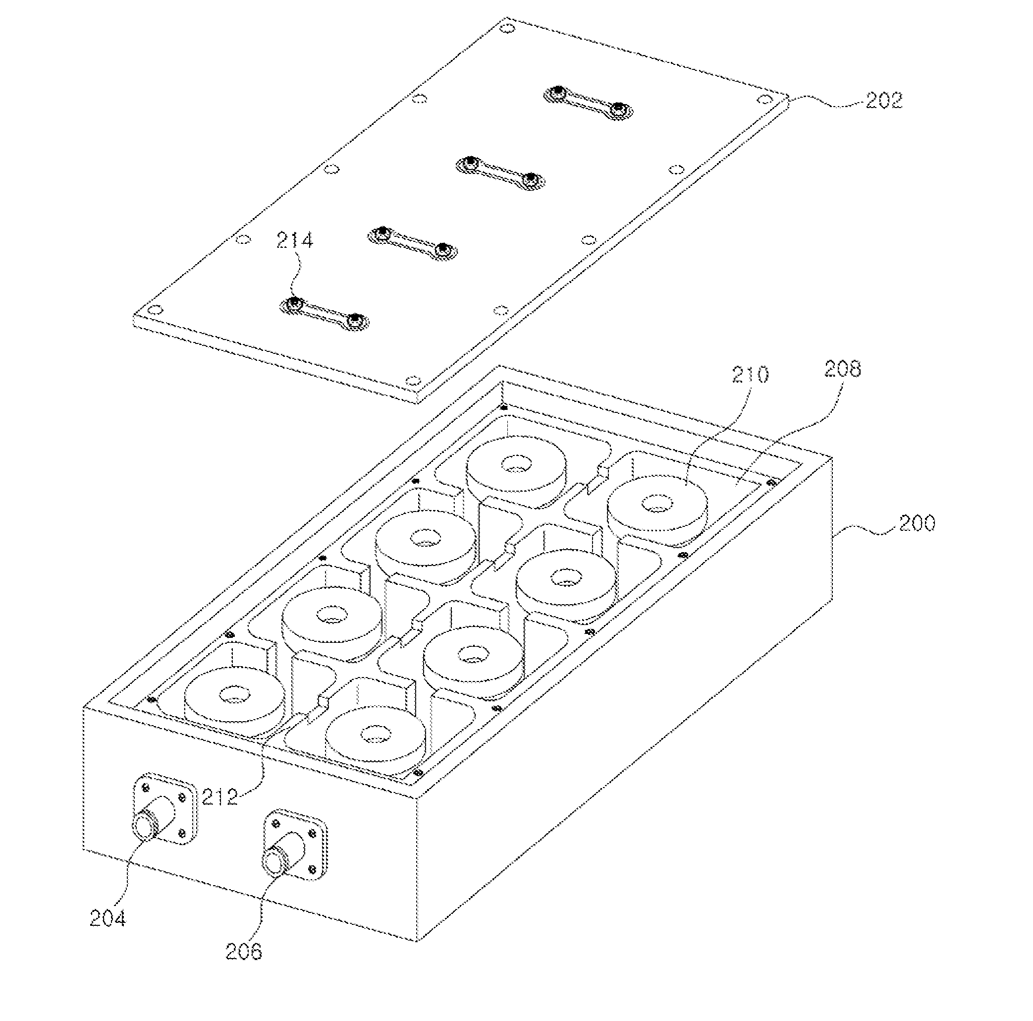
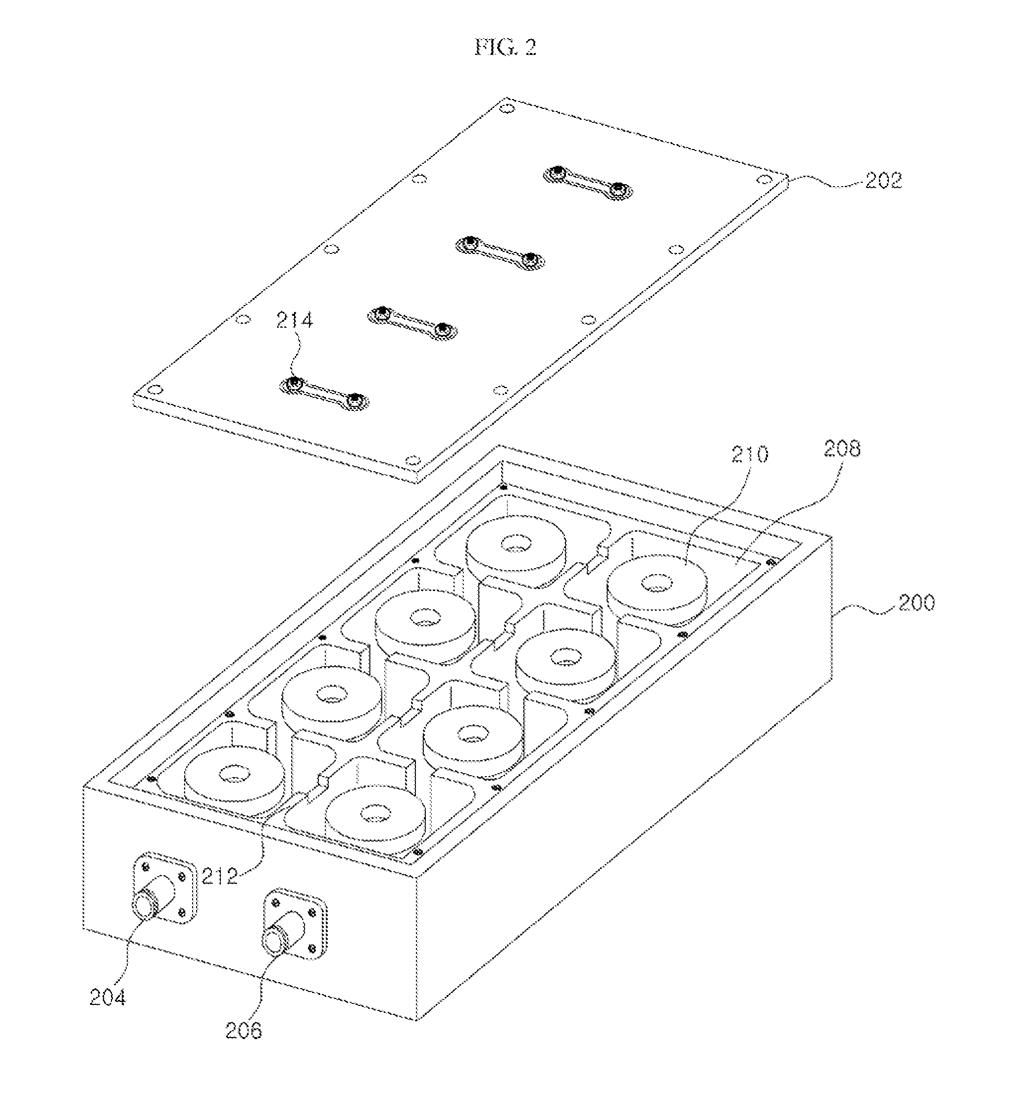
[0040]FIG. 2 is a perspective view illustrating an RF filter according to the present invention.
[0041]In FIG. 2, the RF filter of the present invention is for example an RF cavity filter, and includes a housing member 200, a cover 202, an input connector 204, an output connector 206, cavities 208, resonators 210, walls 212 and tuning elements 214.
[0042]The housing member 200 protects elements in the RF filter, and blocks an electromagnetic wave. The housing member 200 may be formed by coating silver having high conductivity on an aluminum material.
[0043]The cover 202 is combined with an upper surface of the housing member 200, for example may be combined with the upper surface of the housing member 200 through a bolt, etc. The cover 202 may be formed by for example coating silver on aluminum material, and functions as a ground.
[0044]An RF signal is inputted through the input connector 204 and is outputted through the output connector 206. Here, the RF signal propagates through coupl...
second embodiment
[0066]FIG. 9 is a view illustrating schematically structure of an RF filter according to the present invention. FIG. 9 does not show a housing member, resonators, etc.
[0067]In FIG. 9, the RF filter of the present embodiment includes a cover 200, a supporting member 900, tuning elements 902a and 902b and nuts 904a and 904b.
[0068]The supporting member 900 is formed on an upper surface of the cover 200, and may be formed by coating conductive material on a dielectric member.
[0069]A first tuning element 902a is inserted into corresponding cavity through the supporting member 900 and the cover 200, and a second tuning element 902b is inserted into corresponding cavity through the supporting member 900 and the cover 200. Since an upper surface of the supporting member 900 is coated with conductive material, the tuning elements 902a and 902b are connected electrically. However, the tuning elements 902a and 902b are not connected electrically to the cover 202 because a base of the supporti...
third embodiment
[0072]FIG. 10 is a perspective view illustrating an RF filter according to the present invention.
[0073]In FIG. 10, the RF filter of the present invention is for example an RF cavity filter, and includes a housing member 1000, a cover 1002, an input connector 1004, an output connector 1006, cavities 1008, resonators 1010, walls 1012 and a third tuning element 1030.
[0074]Since the housing member 1000, the cover 1002, the input connector 1004, the output connector 1006 the cavities 1008, the resonators 1010 and the walls 1012 are the same in FIG. 2, any further description concerning the same elements will be omitted.
[0075]The third tuning element 1030 is for example a metal, is used for adjusting cross coupling amount or transmission zero, and is disposed on an upper surface of the cover 1002.
[0076]In one embodiment of the present invention, the third tuning element 1030 may be a lumped element such as a capacitor, an inductor, etc.
[0077]Hereinafter, a process of adjusting coupling am...
PUM
 Abstract
Description
Claims
Application Information