Surface penetrating radar system and target zone investigation methodology

a radar system and target zone technology, applied in the field of surface penetrating radar systems, can solve the problems of limiting the penetration distance and reflection time resolution, complex, heavy, etc., and requiring large and expensive aircraft to carry the gpr system

Active Publication Date: 2012-10-04
SANDIA RES CORP
View PDF7 Cites 54 Cited by
  • Summary
  • Abstract
  • Description
  • Claims
  • Application Information

AI Technical Summary

Problems solved by technology

Existing airborne GPR systems are broad band, complex, heavy, and require large and expensive to operate aircraft to carry the GPR systems.
Additionally, the wide bandwidth of conventional GPR systems can cause distortion, i.e., frequency dependent attenuation, and dispersion, i.e., frequency dependent velocity, which can greatly limit the penetration distance and reflection time resolution.

Method used


Image

  • Surface penetrating radar system and target zone investigation methodology
  • Surface penetrating radar system and target zone investigation methodology
  • Surface penetrating radar system and target zone investigation methodology

Examples


Embodiment Construction

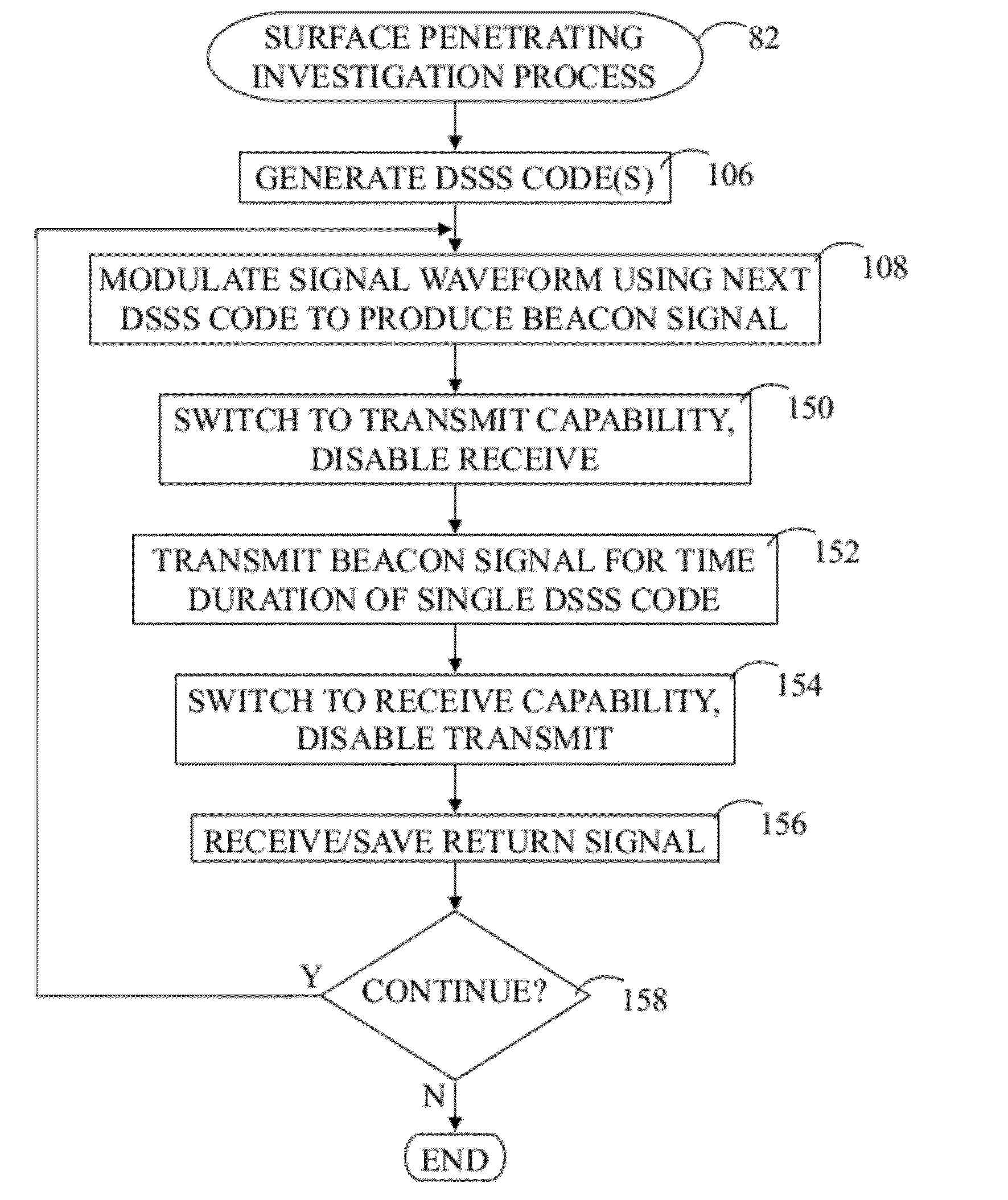
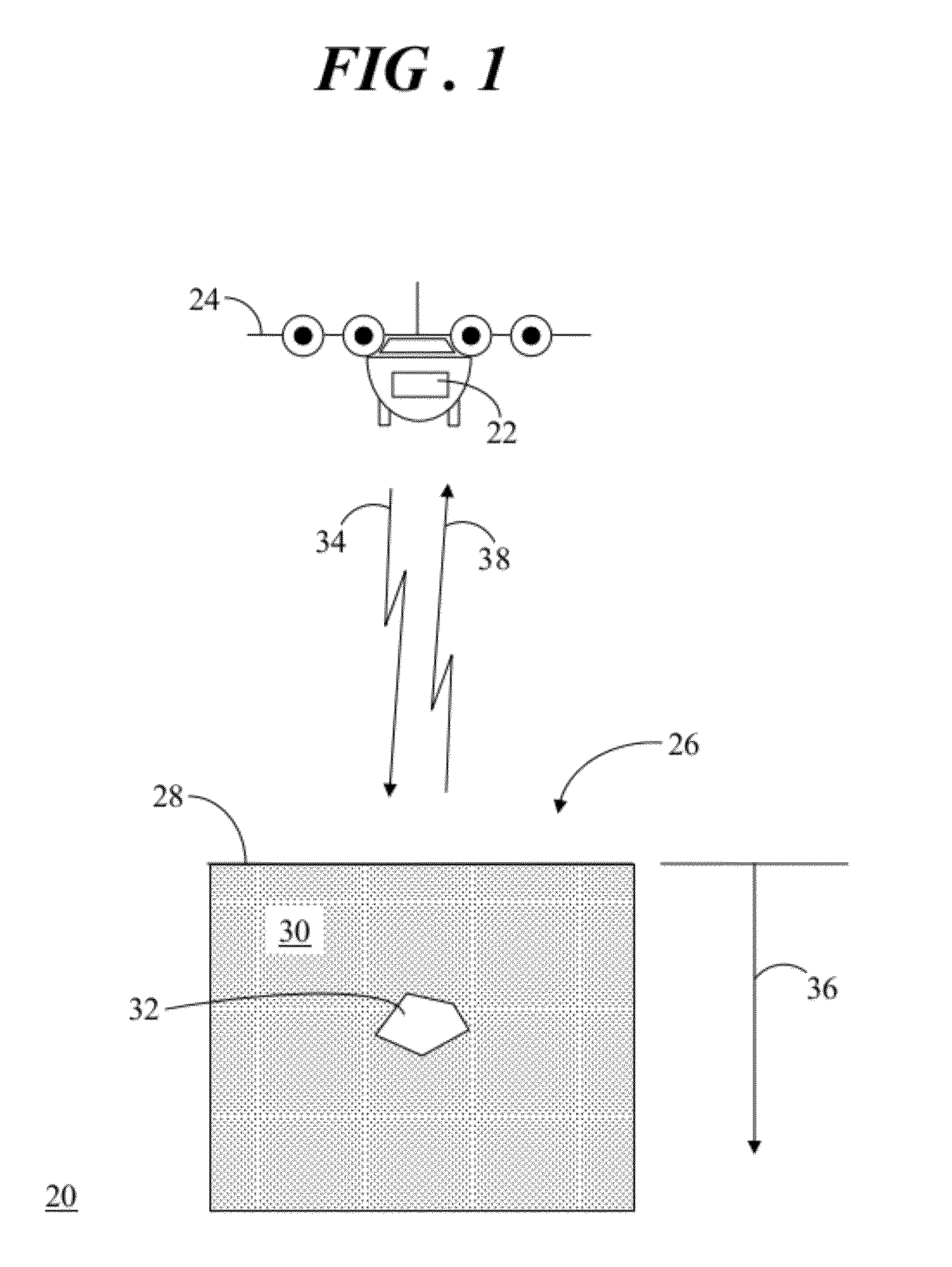
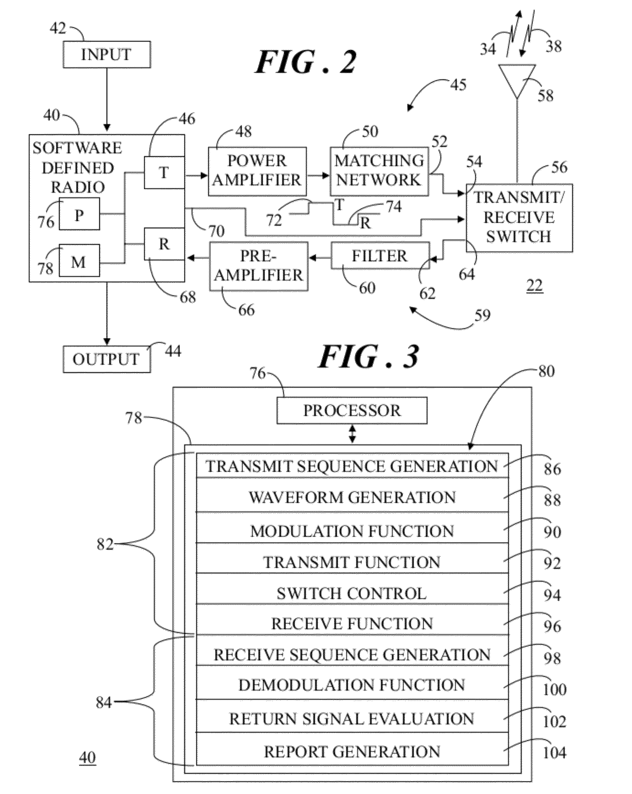
[0015]Embodiments of the invention entail a surface penetrating radar system and associated methodology for investigating the surface and subsurface of a target zone. The radar system and methodology implement a narrow bandwidth direct sequence spread spectrum (DSSS) code. The narrow bandwidth can minimize frequency dependent dispersion and distortion. In addition, the DSSS code enables greater process gains for adaptation to different distances of subsurface penetration and improved reflected signal recovery. A long, DSSS coded, narrow bandwidth radar waveform signal advantageously enables the energy of the waveform to be distributed over the entire DSSS code sequence so that peak power requirements of the transmitter can be greatly reduced. The relatively low peak power requirements of the radar system allow smaller and lighter radar components suitable for airborne applications, such as manned aircraft and unmanned aerial vehicles (UAV).

[0016]FIG. 1 shows a diagram of an environm...


PUM


Abstract

A radar system (22) includes a transmitter (45), a receiver (59), and a software defined radio (SDR) peripheral (40). Methodology (80) for investigating a target zone (26) utilizing the system (22) entails generating (106) a direct sequence spread spectrum (DSSS) code (120) having a code length (122) corresponding to a time duration of radio wave travel between the transmitter (45), the target zone (26), and the receiver (59) at a carrier frequency (112). A beacon signal (34), modulated (108) by the DSSS code (120), is transmitted (152) from the transmitter (45) toward the target zone (26) and a return signal (38) is received (156) at the receiver (56). The return signal (38) is compared (170) to a replica signal (168) characterized by the DSSS code (120), and presence of an object (32) in the target zone (26) is ascertained (178) when the return signal (38) matches the replica signal (168).

Description

TECHNICAL FIELD OF THE INVENTION[0001]The present invention relates to the field of surface penetrating radar systems. More specifically, the present invention relates to a surface penetrating radar system using a spread spectrum methodology for controlling penetration distance.BACKGROUND OF THE INVENTION[0002]Surface penetrating radar, also referred to as ground penetrating radar (GPR), is used to investigate the surface and subsurface features of a target zone or area. In general, GPR uses transmitting and receiving antennas, or only one antenna containing both functions. The transmitting antenna typically radiates short pulses of high-frequency radio waves into the ground. When the wave hits a buried object or a boundary with different electromagnetic properties, the wave is reflected from the object or boundary, and a receiving antenna records the reflected return signal. The return signals can be used to locate and / or construct an image of what is underground because the return...

Claims


Application Information

Patent Timeline
Patent Type & Authority Applications(United States)
IPC IPC(8): G01S13/04
CPCG01S13/04G01S13/885G01S13/288
Inventor SHOPE, STEVEN M.
Owner SANDIA RES CORP
Why Eureka
Try Eureka