Liquid ejecting apparatus and control method thereof

a liquid ejecting and liquid technology, applied in the direction of printing, other printing apparatus, etc., can solve the problems of insufficient discharge of thickened liquid components, difficult to accurately detect the viscosity of ink components that have not thickened within, and the inability to completely rectify the thickening of ink due to evaporation of solvent, etc., to achieve the effect of reducing residual vibration

Inactive Publication Date: 2012-10-04
SEIKO EPSON CORP
View PDF5 Cites 50 Cited by
  • Summary
  • Abstract
  • Description
  • Claims
  • Application Information

AI Technical Summary

Benefits of technology

[0006]A liquid ejecting apparatus according to an aspect of the invention includes: a liquid ejecting head, having a pressure chamber filled with a liquid and a pressure generation element that causes the pressure of the liquid within the pressure chamber to fluctuate, that is capable of executing ejection driving that ejects the liquid from the nozzle based on the pressure fluctuation in the liquid within the pressure chamber; a driving waveform generation unit that generates a driving waveform for executing the ejection driving; a control unit that causes the liquid ejecting head to execute a flushing operation that discharges the liquid within the pressure chamber; and a residual vibration detection unit that detects a residual vibration in the liquid within the pressure chamber. The control unit corrects the driving waveform based on the residual vibration produced by the flushing operation. According to this configuration, residual vibrations in the liquid produced by the flushing operation are detected, and thus influence of thickened components within the pressure chamber on the residual vibrations can be reduced; this makes it possible to more suitably correct the driving waveform.
[0007]According to another aspect of the invention, it is preferable that the control unit calculate a characteristic value indicating a characteristic of the liquid based on the residual vibration produced by the flushing operation, and correct the driving waveform based on the characteristic value. According to this configuration, the driving waveform is corrected based on the characteristic value calculated based on the residual vibration, and thus the correction of the driving waveform is more suitable.
[0009]With a configuration in which the amount of liquid that is ejected is constant in the flushing operation regardless of the characteristic value of the liquid, there is a chance that the thickened components of the liquid will not be sufficiently discharged, or a chance that an excessive amount of liquid will be discharged. According to the aforementioned configuration, the first characteristic value is calculated based on the residual vibrations produced by the first flushing operation, and the second flushing operation that ejects an amount of liquid based on the first characteristic value is then executed. The thickened components in the pressure chamber are thus sufficiently discharged even in the case where the viscosity of the liquid has increased. Accordingly, the characteristic value of the liquid that reduces the influence of the thickening can be calculated, and thus the driving waveform can be corrected in a more appropriate manner. Meanwhile, an excessive amount of liquid is suppressed from being ejected in the second flushing operation in the case where the viscosity of the liquid has decreased, which further reduces the amount of liquid that is consumed.
[0011]With a configuration that determines the amount of liquid to be ejected in the second flushing operation based only on the characteristic value in the current adjustment period, there is a chance, in the case where the liquid within the pressure chamber has suddenly thickened between a past adjustment period and the current adjustment period, that the thickened components of the liquid cannot be sufficiently discharged through the second flushing operation in the current adjustment period. According to the aforementioned configuration, the amount of liquid to be ejected in the second flushing operation of the current adjustment period is determined in accordance with a result of comparing a characteristic value (the first characteristic value or the second characteristic value) of a past adjustment period with the first characteristic value of the current adjustment period. It is thus easier to discharge a sufficient amount of thickened components from within the pressure chamber, even in the case where the liquid within the pressure chamber has suddenly thickened. Accordingly, the characteristic value of the liquid that reduces the influence of the thickening can be calculated, and thus the driving waveform can be corrected in a more appropriate manner.
[0013]According to another aspect of the invention, it is preferable that the liquid ejecting apparatus further include a heating device that heats the ejected liquid. According to this configuration, the characteristics of the liquid change more easily due to the heating performed by the heating device, and thus the effects achieved by the aforementioned configurations are even more prominent.

Problems solved by technology

It is possible that such a thickening of the ink due to evaporation of the solvent will not be completely rectified within the period in which printing operations are carried out.
Accordingly, using the technique in JP-A-2006-35812 that detects the viscosity of ink during periods in which printing is carried out, it is difficult to accurately detect the viscosity of ink components that have not thickened within the pressure chamber (that is, a viscosity resulting from a cause aside from the stated thickening).
With a configuration in which the amount of liquid that is ejected is constant in the flushing operation regardless of the characteristic value of the liquid, there is a chance that the thickened components of the liquid will not be sufficiently discharged, or a chance that an excessive amount of liquid will be discharged.
With a configuration that determines the amount of liquid to be ejected in the second flushing operation based only on the characteristic value in the current adjustment period, there is a chance, in the case where the liquid within the pressure chamber has suddenly thickened between a past adjustment period and the current adjustment period, that the thickened components of the liquid cannot be sufficiently discharged through the second flushing operation in the current adjustment period.

Method used


Image

  • Liquid ejecting apparatus and control method thereof
  • Liquid ejecting apparatus and control method thereof
  • Liquid ejecting apparatus and control method thereof

Examples


first embodiment

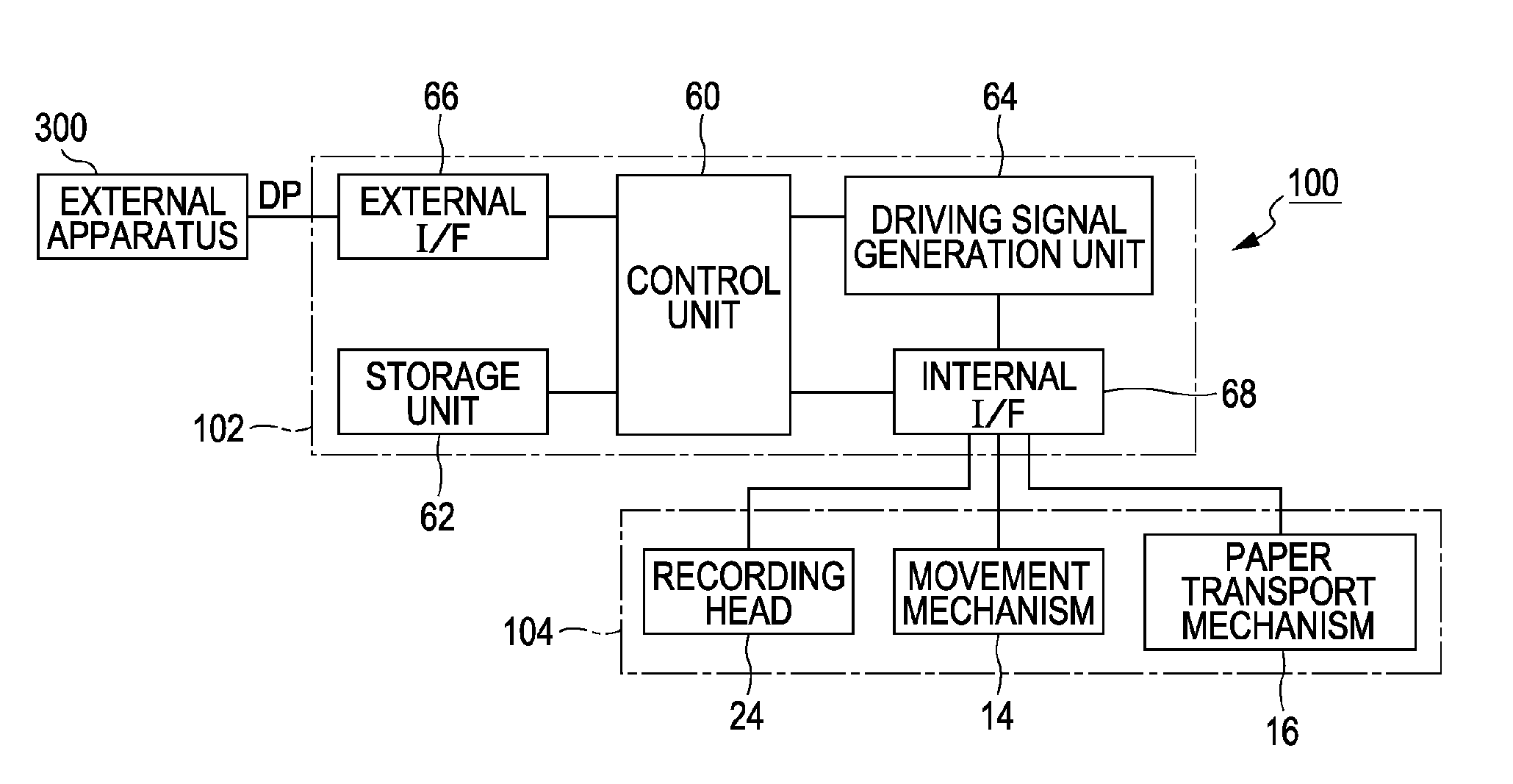
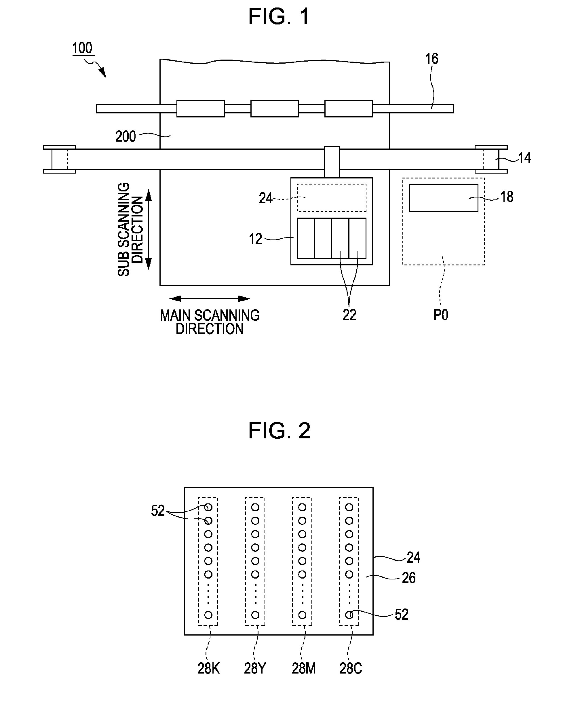
[0036]FIG. 1 is a partial schematic diagram illustrating an ink jet printing apparatus 100 according to a first embodiment of the invention. The printing apparatus 100 is a liquid ejecting apparatus that ejects ink droplets onto recording paper 200, and includes a carriage 12, a movement mechanism 14, and a paper transport mechanism 16.

[0037]Ink cartridges 22 and a recording head 24 are mounted in the carriage 12. The ink cartridges 22 are receptacles that hold ink (liquid) to be ejected onto the recording paper 200. The recording head 24 functions as a liquid ejecting head that ejects the ink held in the ink cartridges 22 onto the recording paper 200. Note that a configuration in which the ink cartridges 22 are fixed to a housing (not shown) of the printing apparatus 100 and the ink is supplied to the recording head 24 therefrom can also be employed.

[0038]FIG. 2 is a plan view of an ejection surface 26 of the recording head 24 that faces the recording paper 200. As shown in FIG. 2,...

second embodiment

[0061]A second embodiment of the invention will be described next. Note that for elements in the following embodiments that have the same effects, functions, and so on as those in the first embodiment, the reference numerals referred to in the above descriptions will be applied, and detailed descriptions thereof will be omitted as appropriate.

[0062]FIG. 14 is an example of a flow of operations through which the control unit 60 according to the second embodiment corrects the driving signal COM in the adjustment period RFL. In the second embodiment, a first flushing operation (step S201) and a second flushing operation (step S206) are executed. An amount of ink based on the result of the first flushing operation is ejected in the second flushing operation.

[0063]When the printing period RDR ends and the adjustment period RFL begins, the control unit 60 connects the piezoelectric element 45 to the driving circuit 322 by controlling the switching circuit 326, and furthermore supplies the...

third embodiment

[0065]FIG. 16 is an example of a flow of operations through which the control unit 60 according to a third embodiment corrects the driving signal COM in the adjustment period RFL. As in step S201 to step S204 in the second embodiment, when the printing period RDR ends and the adjustment period RFL starts, the control unit 60 executes the first flushing operation, and calculates a characteristic value Cvc in the current printing period RDR based on the residual vibrations Rv produced by the Mth ejection driving (step S301 to step S304). The control unit 60 determines the number N of ejection drivings in the second flushing operation in accordance with a difference Δ (Δ=Cvc−Cvp) between the current characteristic value Cvc and a characteristic value Cvp calculated after the flushing operation (the first flushing operation or the second flushing operation) performed in the previous adjustment period RFL (step S305). Specifically, in the case where the difference Δ exceeds a threshold T...


PUM


Abstract

A liquid ejecting apparatus includes: a liquid ejecting head, having a pressure chamber filled with a liquid, and a pressure generation element that causes the pressure of the liquid within the pressure chamber to fluctuate that ejects the liquid from a nozzle based on the pressure fluctuation in the liquid within the pressure chamber; a driving waveform generation unit that generates a driving waveform for ejects the liquid; a control unit that causes the liquid ejecting head to execute a flushing operation that discharges the liquid within the pressure chamber; and a residual vibration detection unit that detects a residual vibration in the liquid within the pressure chamber. The control unit calculates a characteristic value in accordance with a characteristic of the liquid based on the residual vibration produced by the flushing operation, and corrects the driving waveform based on the characteristic value.

Description

BACKGROUND[0001]1. Technical Field[0002]The present invention relates to techniques for ejecting a liquid such as ink.[0003]2. Related Art[0004]Liquid ejection techniques in which a liquid (such as ink) within a pressure chamber is pressurized by a pressure generation element such as a piezoelectric vibrator, a heating element, or the like and ejected from a nozzle have been proposed in the past. Because the ejection characteristics (ejection velocity, ejection amount, and so on) change depending on the temperature, viscosity, and so on of the ink within the pressure chamber, it is preferable for such a liquid ejection technique to employ a configuration that controls the ejection based on the temperature, viscosity, and so on of the ink. For example, JP-A-2006-35812 employs a technique that detects the viscosity of ink by measuring the resonance frequency or antiresonance frequency of a piezoelectric element and determines a driving voltage for the piezoelectric element based on th...

Claims


Application Information

Patent Timeline
Patent Type & Authority Applications(United States)
IPC IPC(8): B41J29/38
CPCB41J2/0454B41J2/04555B41J2/04581B41J2002/14354B41J2/0459B41J2/16526B41J2/04588
Inventor TAKANO, KOJIOZAWA, KINYA
Owner SEIKO EPSON CORP
Why Eureka
Try Eureka