Multiplexer and Modulation Arrangements for Multi-Carrier Optical Modems

a multi-carrier optical modem and modulation arrangement technology, applied in multiplex communication, electrical apparatus, wavelength-division multiplex systems, etc., can solve the problems of high rate modulation formats, inefficient use of optical fiber bandwidth or spectrum, and a higher rate of modulation

Active Publication Date: 2012-10-04
INFINERA CORP
View PDF2 Cites 81 Cited by
  • Summary
  • Abstract
  • Description
  • Claims
  • Application Information

AI Technical Summary

Benefits of technology

[0006]Consistent with one aspect of the present disclosure, an apparatus comprises a first optical transmitter that is configured to supply a plurality of first optical signals, each of the plurality of first optical signals being modulated in accordance with a first modulation format. The plurality of first optical signals collectively have an associated data rate, and each of the plurality of first optical signals have a corresponding one of a plurality of first wavelengths, a highest one of the plurality of first wavelengths and a lowest one of the plurality of first wavelengths defining a first optical bandwidth. A second optical transmitter is configured to supply a plurality of second optical signals, each of the plurality of second optical signals being modulated in accordance with a second modulation format. The plurality of second optical signals collectively have the same data rate as the plurality of first optical signals, and each of the plurality of second optical signals have a corresponding one of a plurality of second wavelengths, a highest one of the plurality of second wavelengths and a lowest one of the plurality of second wavelengths defining a second optical bandwidth that is less than the first optical bandwidth. Also provided is an optical combiner configured to receive the plurality of first optical signals and the plurality of second optical signals, to combine the plurality of first optical signals and the plurality of second optical signals, and supply the plurality of first optical signals and the plurality of second optical signals to an optical communication path.

Problems solved by technology

At 50 GHz channel spacing and 100 GHz channel spacing, the occupied optical fiber bandwidth or spectrum is not efficiently used.
Such higher rate modulation formats, however, are typically more susceptible to noise, and, therefore, may not be used in transmission of optical signals over relatively long distances.
However, the dense packing of individual channels at a reduced spectral spacing between channels has lead to challenges in reliably separating the individual channels at a receive end and increases error rates for the channel due to cross-talk between the adjacent channels or cross-phase modulation effects, for example.
Thus, there is a tradeoff between optical communication system performance and the number of channels to be transmitted per fiber and their spectral spacing, as well as the modulation performed on each of the channels.

Method used


Image

  • Multiplexer and Modulation Arrangements for Multi-Carrier Optical Modems
  • Multiplexer and Modulation Arrangements for Multi-Carrier Optical Modems
  • Multiplexer and Modulation Arrangements for Multi-Carrier Optical Modems

Examples


Embodiment Construction

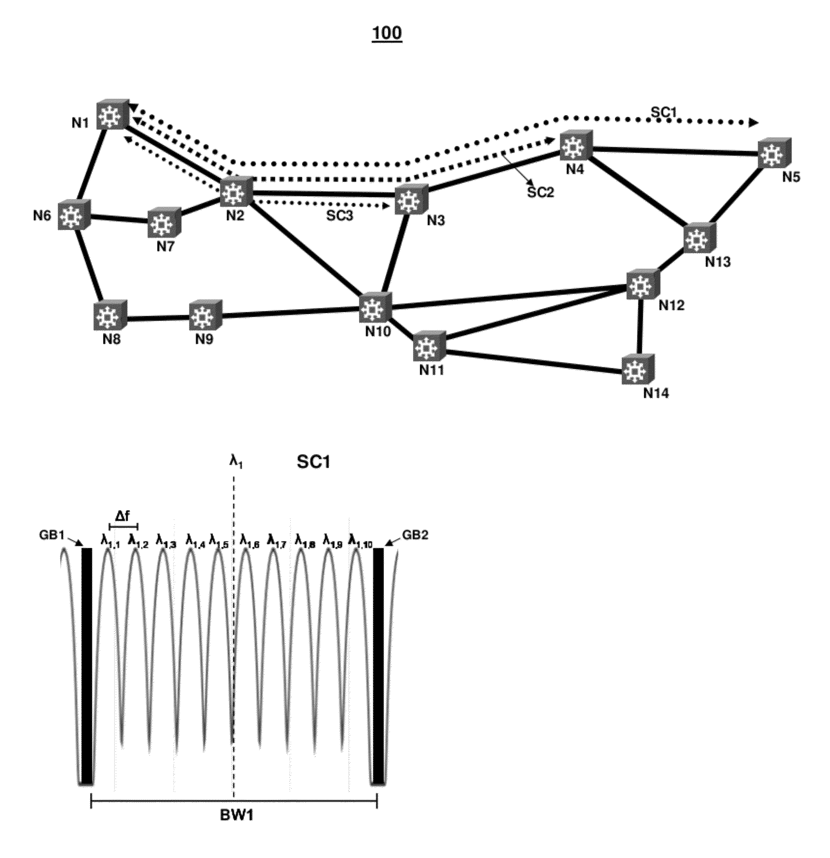
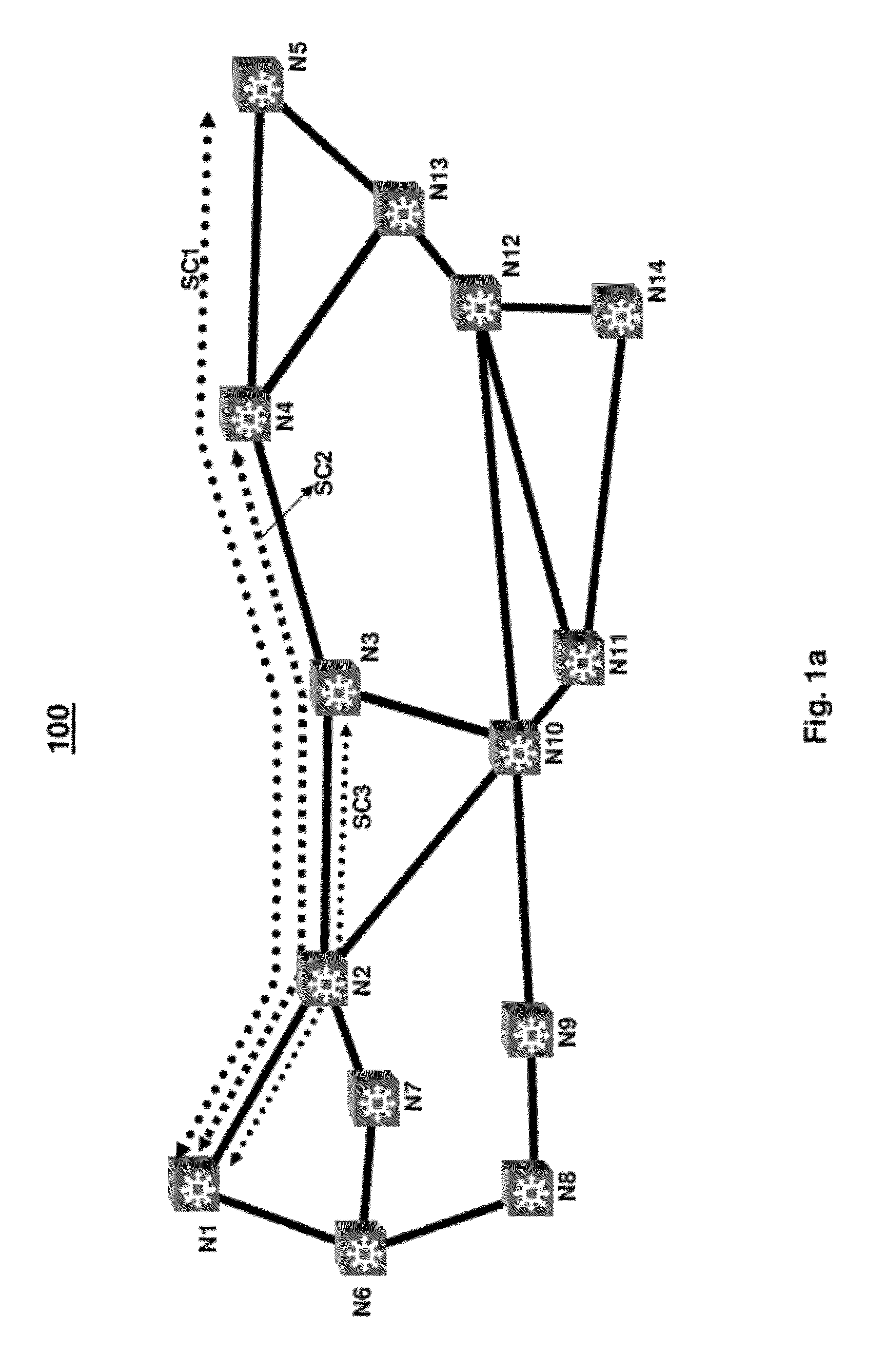
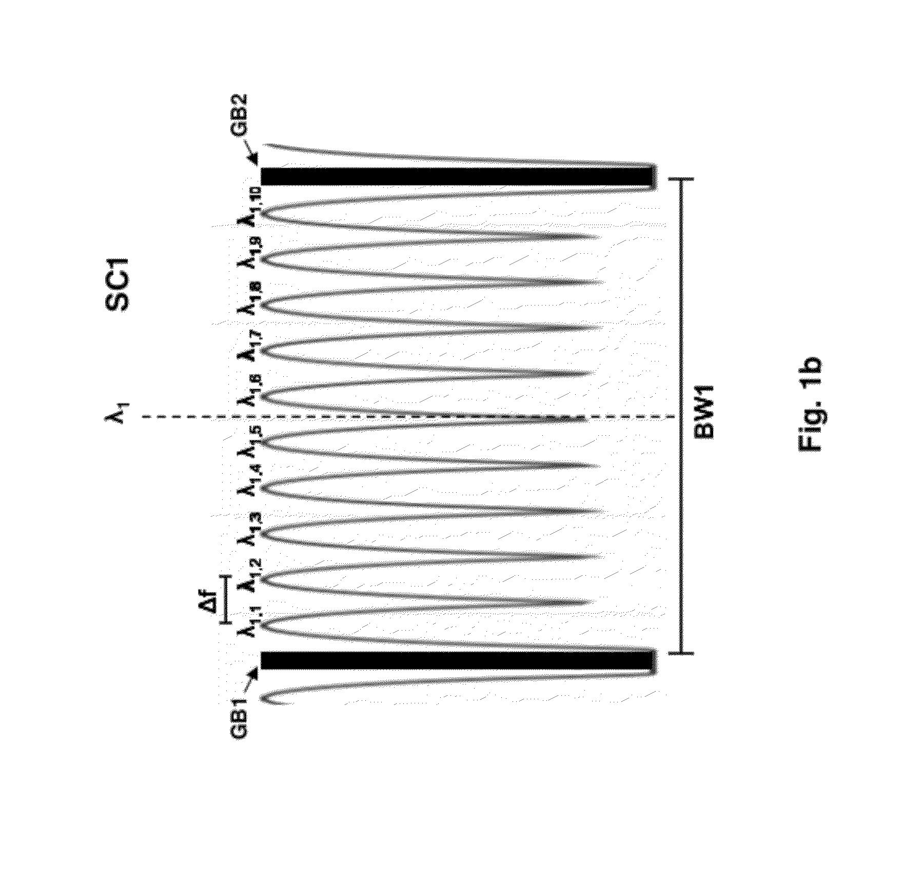
[0026]Consistent with the present disclosure, data, in digital form, is received by a transmit node of an optical communication system, and converted to an analog signal by a digital-to-analog converter (DAC) to drive a modulator. The modulator, in turn, modulates light at one of a plurality of minimally spaced wavelengths in accordance with the received data and a specified modulation format. The plurality of minimally spaced wavelengths or carriers are grouped together with a fixed spacing combiner, for example, to form a superchannel. A plurality of superchannels are then multiplexed and transmitted over an optical communication path to a receive node. At the receive node, the multiplexed superchannels are demultiplexed by an optical demultiplexer and provided to a plurality of corresponding demodulators. Prior to demodulation, each superchannel may be demultiplexed using one or more filter based demultiplexers to separate the plurality of minimally spaced carriers. The demultipl...


PUM


Abstract

Consistent with the present disclosure, data, in digital form, is received by a transmit node of an optical communication, and converted to analog signal by a digital-to-analog converter (DAC) to drive a modulator. The modulator, in turn, modulates light at one of a plurality of wavelengths in accordance with the received data forming a plurality of corresponding carriers. The plurality of carriers are then optically combined with a fixed spacing combiner to form a superchannel of a fixed capacity. Accordingly, the number of carriers are selected according to a modulation format and symbol rate to realize the fixed capacity, for example. The superchannel is then transmitted over an optical communication path to a receive node. At the receive node, the superchannel is optically demultiplexed from a plurality of other superchannels. The plurality of carriers are then supplied to a photodetector circuit, which receives additional light at one of the optical signal carrier wavelengths from a local oscillator laser. An analog-to-digital converter (ADC) is provided in the receive node to convert the electrical signals output from the photodetector into digital form. The output from the ADC is then filtered in the electrical domain, such that optical demultiplexing of the carriers is unnecessary.

Description

BACKGROUND OF THE DISCLOSURE[0001]Wavelength division multiplexed (WDM) optical communication systems are known in which multiple optical signals or channels, each having a different wavelength, are combined onto an optical fiber. Such systems typically include a laser associated with each wavelength, a modulator configured to modulate the optical signal output from the laser, and an optical combiner to combine each of the modulated optical signals. Such components are typically provided at a transmit end of the WDM optical communication system to transmit the optical signals onto the optical fiber. At a receive end of the WDM optical communication system, the optical signals are often separated and converted to corresponding electrical signals that are then processed further.[0002]Known WDM optical communication systems are capable of multiplexing 40 channels at 100 GHz spacing or 80 channels at 50 GHz spacing. These WDM optical communication systems occupy an overall bandwidth of ...

Claims


Application Information

Patent Timeline
Patent Type & Authority Applications(United States)
IPC IPC(8): H04J14/02
CPCH04J14/02H04J14/06H04J14/026H04J14/0256
Inventor MCNICOL, JOHN D.MITCHELL, MATTHEW L.WELCH, DAVID F.
Owner INFINERA CORP
Why Eureka
Try Eureka